Imagine you just got hired to develop the race car setup in a new racing team. They are inexperienced, but willing to do what it takes to win. Also, they got the cash to boost their performance, they just don’t know what to do with it, hence, they hired you.
First day in the shop, team manager comes and tells you the team is under a lot of pressure to perform, because their sponsors saw them as a risky investment. Initially they were unwilling to take the risk, but the manager was able to convince them, under the condition that the team would be in the top 5 in the category.
The sponsors brought in a really quick, but demanding and rigorous driver. The guy is experienced in the series your team will race, and since he was able to consistently deliver performance for the past 5 years, if he doesn’t do it this time, the blame will fall upon your team, which will not only make your current sponsors quit, but will make it harder to find new sponsors or even gentlemen drivers.
The series your team will race is a single-make category, so you can’t implement design improvements. However, the race car setup is quite open, and the car has many adjustable parameters. Now the ball is in your court. How would you make their car faster? If you are an engineer worth your team’s money, you’d resort to performance engineering.
WHAT IS PERFORMANCE ENGINEERING?
Performance engineering is the branch of motorsport engineering that focuses on performance improvement of the race car/driver combination. Performance engineers might be involved in many aspects of the development, such as design, testing and setup, with a stronger focus on the last two. In general, performance engineering contributions to the design of the car come as guidelines for improvement, based on performance analysis of previous race and test events.
TOOLS OF PERFORMANCE ENGINEERING
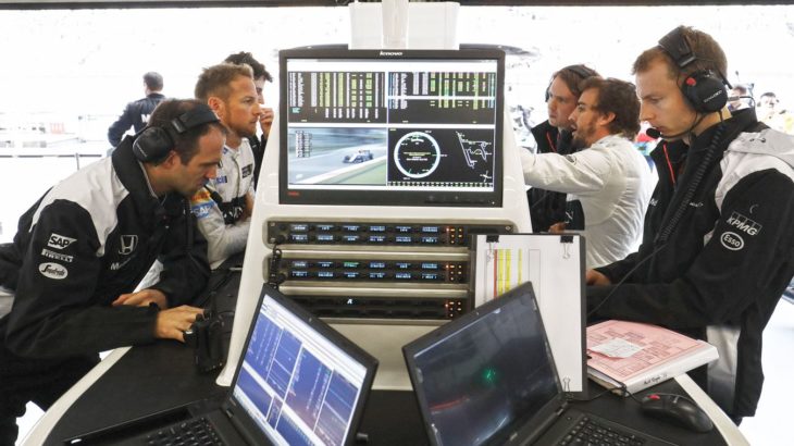
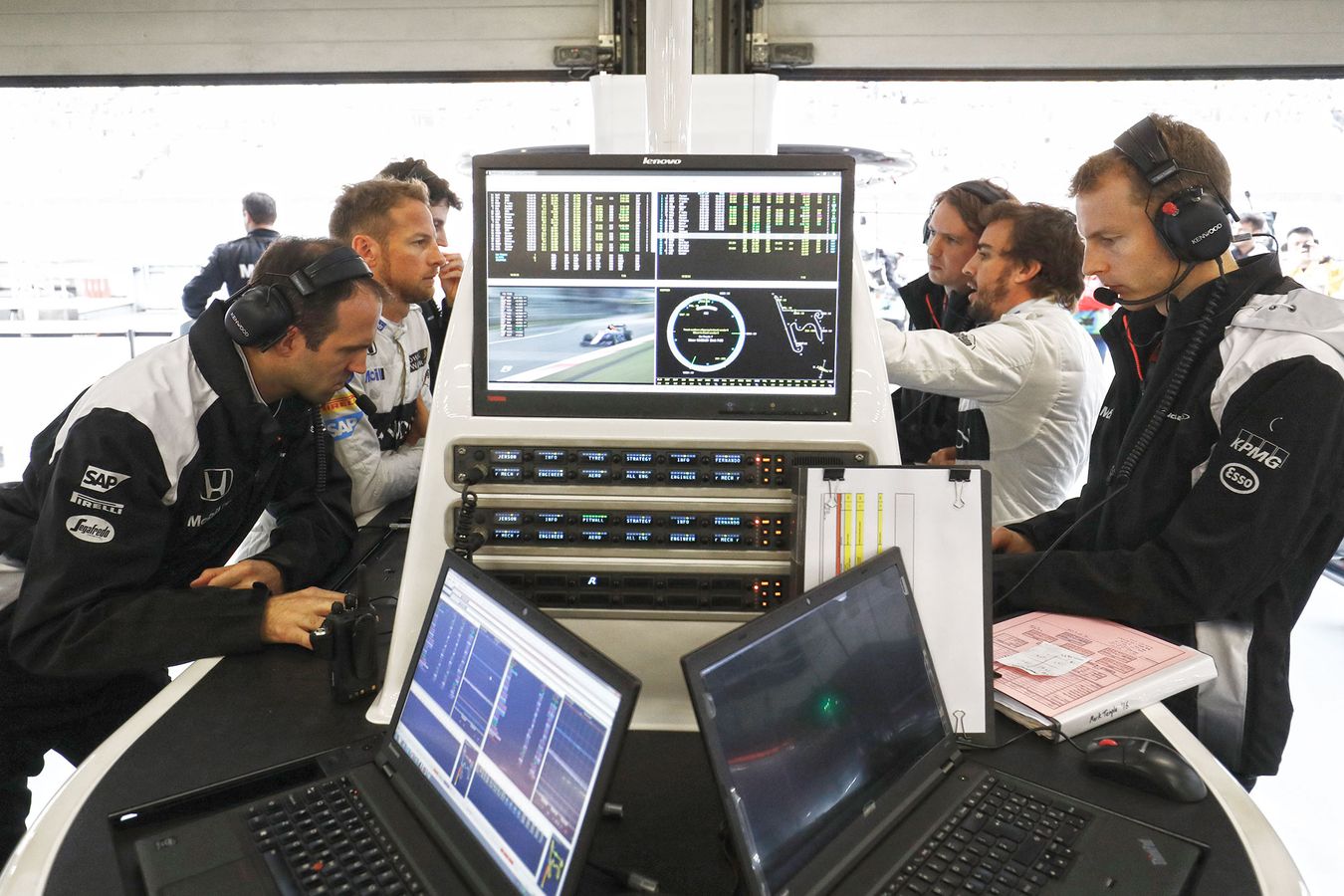
As I mentioned in the post about how to make a career as a motorsport engineer, a great way to find out what are the skills needed to do a particular engineering job is to look at the requirements in vacancy posts related to that function. So, in order to introduce the most useful tools in performance engineering, I’ll bring some job posts here. These come from Motorsportjobs.com and RaceStaff.
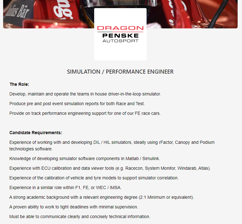
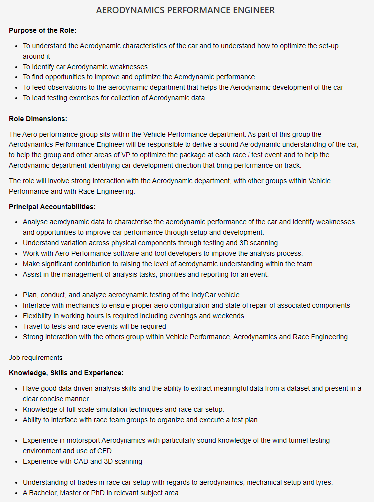
From the job posts above, you can see many common points, apart from the obvious engineering graduation, some software specificity, and soft skills. In all vacancies, the performance engineer will either be responsible for the development of the setup of the car, or he will give some input into it. Notice that there are specific performance engineering jobs, as it’s the case for the aerodynamics performance engineer in McLaren. Other specific functions include tire performance engineer and engine performance engineer.
Looking into the job posts, I can identify three key technical points, which appear in one way or another in all four of them. They are experimentation, simulation, and data analysis. Let’s have a deeper look at all of them.
Experimentation
Experimentation appears in the posts in many forms, such as “Experience of the [sic] calibration of vehicle and tyre models to support simulator correlation” for Dragon Penske, as “To lead testing exercises for collection of Aerodynamic data” for McLaren Racing, as “Familiar with systematic design of experiments” for Honda Performance Development and as “Participate in different test and event activities” for Hyundai Motorsport.
Experimentation is a fundamental part of the vehicle’s characterization process, in which real-world data is collected to serve in simulations as either input or validation means. Experimental methods in performance engineering include measuring parameters of the car in the workshop, taking the race car (or a part of it) to an experimental rig such as a wind tunnel, an engine dynamometer, or a post shaker rig, or it can be testing on the track, either in controlled or race-like conditions.
Vehicle characterization can be done at a macro level, where we are more interested in aspects such as tire grip, engine performance or aerodynamic performance, and at a micro level, where we look at how the systems of the car interact with the macro aspects (e.g. how the suspension kinematics affects tire grip, and how vehicle ride height affects downforce).
The performance engineer should be able to plan and execute tests and experiments to collect information about the car, in order to improve accuracy of vehicle models, and to gain a thorough understanding of how the car responds to changes in setup and race conditions (tire wear, fuel load, etc).
Simulation
As you can see from all job posts, simulation is a fundamental tool in performance engineering. Whether you are using CFD, quasi-steady lap time or drive-in-the-loop simulations, the application of this tool is one of the most important parts of the job of a performance engineer.
If you read the previous post in the Racing Car Dynamics about this subject, you know that there are many different applications and levels in which simulation is applied in racing. You can use it to measure the effect of setup changes, to understand how the behavior of the car changes under different racing conditions, to study race strategies, and so on. If you haven’t read the aforementioned post, I totally recommend that you do, because it’s a thorough explanation of the subject.
Simulation is an invaluable tool in pre-event preparation. For this, we run simulations with many setup configurations, and we try to understand the effect of setup changes on vehicle performance. For example, a performance engineer will run simulations and test different levels of ride height and floor rake (assuming the car has ground effect aerodynamics), trying to understand how these parameters are affected by suspension stiffness (which influences ride height), and how all things combined improve performance.
Data analysis
The experimentation and simulation tools will provide you with tons of data about the performance of the driver/car combination. What’s the point of having all this data if you don’t know what to do with it? Hence, the importance of data analysis.
Whether you are analyzing data about the car or the driver, motorsport data analysis will have lots of techniques which aren’t transferable to other engineering areas. If you are interested in that, you can learn these techniques in my course, Fundamentals of Motorsport Data Analysis.
When you are analyzing data in motorsport, you generally will be working with industry specific data analysis software, such as MoTeC i2, Pi Toolbox, Wintax, WinDarab, McLaren Atlas, etc. These software generally will have lots of features in common, so learning one software will generally make it easier to learn others, at least to an intermediate level.
ELEMENTS OF RACE CAR PERFORMANCE
One cannot talk about performance engineering without talking about the performance elements of a race car. There are four major elements: braking, cornering, grip limited acceleration, and power/drag limited acceleration.
These elements combine to produce the lap time of the car. Generally, the car will spend more time in the elements with lower speed, i.e. braking, cornering and grip limited acceleration. Therefore, an improvement in these elements will normally result in smaller lap times. Of course, exceptions exist. For example, a lap in Monza has so much time spent in wide open throttle conditions that you will likely be better off by increasing your power or reducing your drag as opposed to increasing your downforce or tire grip.
Obviously, you only have to choose when these factors go against each other (for example, increasing downforce will likely increase drag, so an improvement in cornering and braking will likely cost in high-speed accelerations), otherwise, improve as many factors as you can, focusing on the ones with higher impact on lap time first. Now let’s have a more in-depth look at the parameters that affect these performance elements.
From all four elements, three are majorly influenced by tire performance. They are braking, cornering and grip limited acceleration. Tire performance on the other hand is largely influenced by its orientation, load, and pressure.
Tire Orientation
This refers to the angles the tire makes with the ground, i.e. camber and toe-in/steer angle. The latter is one of the causes of slip angle (the other being the motion of the car itself, more specifically, the yaw rate, chassis slip angle, and vehicle speed) and both are directly related to tire force and wear.
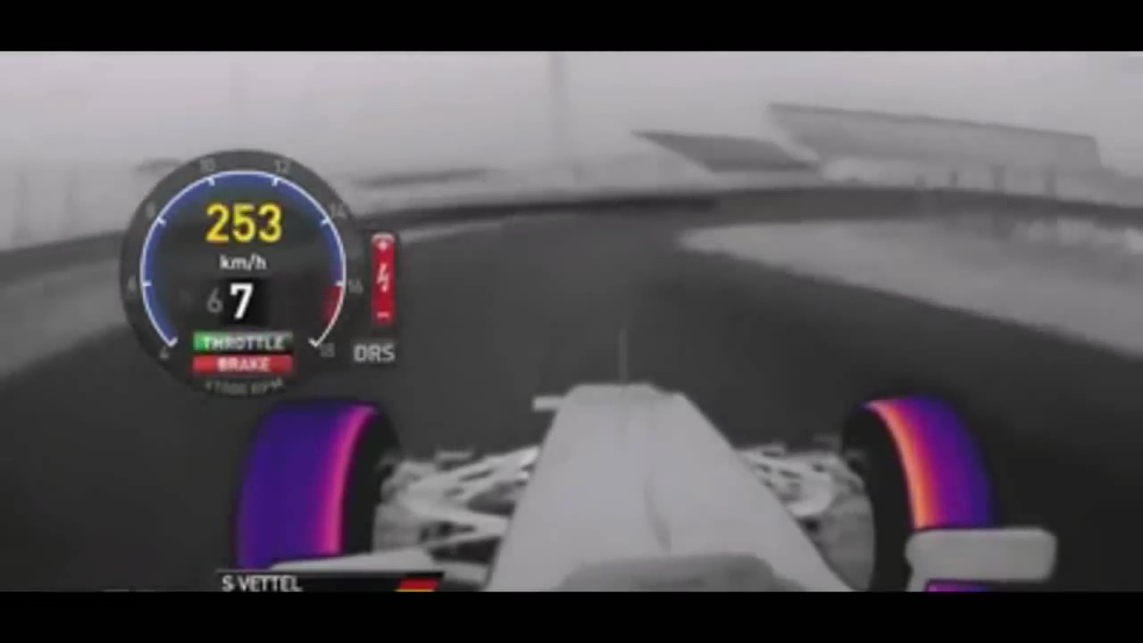
Tire orientation is controlled by suspension kinematics. That’s why the suspension geometry must be carefully designed in order to provide the desired tire orientation. As an example, look at the image sequence below. They show a thermal camera shot of the tires from Sebastian Vettel in Suzuka, 2013. If you aren’t used to thermal cameras, here’s a quick guide: in the scale shown, the colors closer to yellow represent higher temperatures, while the colors closer to purple/blue represent the lower ones. The points in greyscale don’t represent any temperature.
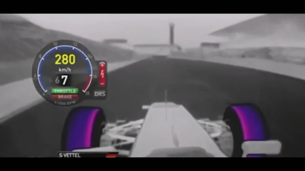
In the image above, the car is in a straight line, at a relatively high speed. You can see higher temperature on the inside of the tires. This is due to static camber, which is generally negative (meaning that the top of the tire leans towards the center of the car).
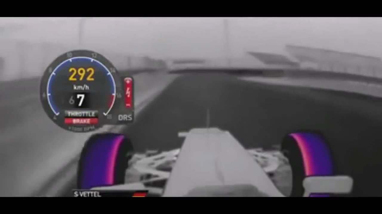
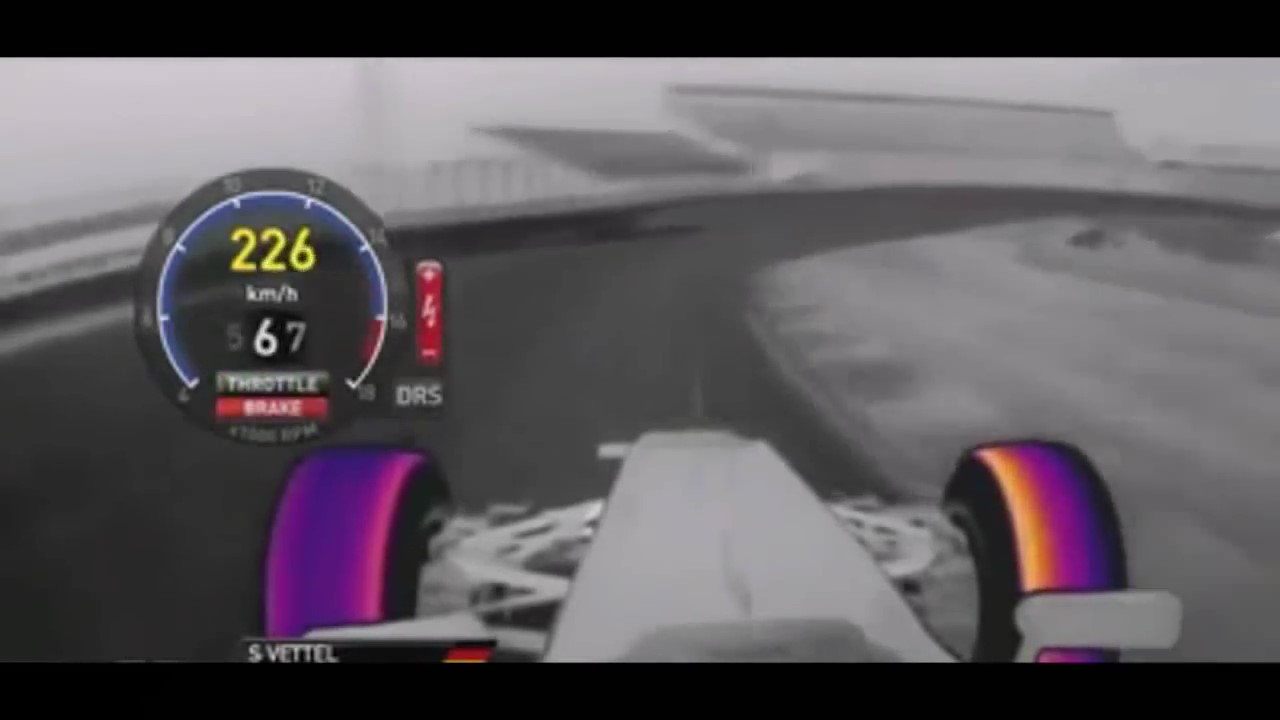
Here is the beginning of the braking phase (the car is at a higher speed, but you can see in the graphics that the brakes are fully applied). Now we can see an increase in temperature of the tires, but still only on the inside of the tire tread.
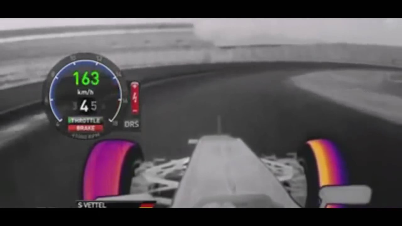
This is the beginning of the turn-in phase, you can see initially that the temperature increases on the inside tire first. At this point, we have little to no lateral load transfer, since the lateral acceleration is still too low.
Now we have a little more lateral acceleration, the tires heat up a lot, in comparison with the straight-line case. Now we begin to see lateral load transfer beginning to occur, as we have more temperature in the outside tire.
The car now begins to approach the steady state phase. We can notice a much more uniform temperature in the outside tire, although this temperature is still lower than on the inside tire.
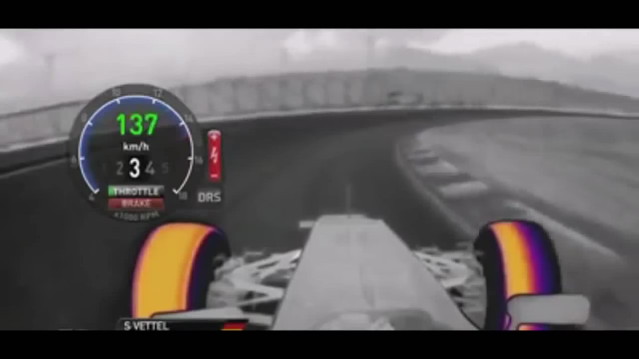
At last, the car reaches full steady state. Now we can see very high temperatures on the outside tire. This is due to lateral load transfer. Notice that now the outside tire, which has a much higher load on it (and hence, produces much more lateral force) than the inner tire, has a uniform temperature distribution across its tread.
The reason for this behavior is that suspension kinematics is designed to give a neutral camber in the outside tire at maximum cornering grip situations. A neutral camber during the corner increases contact patch area, reducing wear and improving grip. The design of the suspension geometry has to consider three main aspects: static geometry, the variation of geometry parameters with suspension travel, and the variation of geometry with deflection of suspension members (called compliance).
Tire load
This refers to the vertical forces acting upon the tires. The main aspects that influence tire load are aerodynamics, tire load fluctuation, and load transfer. Race car aerodynamics is designed to produce downforce through elements such as wings, ground effect and vortex control. It is the most important factor when it comes to tire load augmentation, and hence, it’s one of the most important aspects of race car performance.
Tire load fluctuation is controlled by suspension vibration dynamics, i.e., the oscillatory travel of the wheels, regulated by elements such as springs, dampers, inerters, and so on. Careful control of suspension dynamics can’t increase instantaneous tire load, however, it can reduce load fluctuation, which results in a higher average load (and hence, higher average grip).
The way this works is that track surface has some roughness and elevation changes, which will push the tires up and down, as the car moves around the track. The suspension should compress and extend quickly enough to allow this movement, which requires a softer setup. If the suspension is too stiff, the wheel can’t travel quickly enough, so that the tire will “bounce” and lose contact with track surface, which decreases its load.
The tire will not necessarily stop touching the track, for its load to decrease, even small upward movements which don’t copy the track profile are enough to produce a significant load reduction. There is an important tradeoff here: while a softer suspension allows for better track unevenness absorption, it results in poor body motion control. This, in turn, creates a twofold problem: it generates higher kinematics variation because suspension travel is larger (therefore it will be harder to maintain optimum tire orientation) and the aerodynamic floor (when it is present) will run on higher roll and pitch angles, and heights, likely losing downforce.
Load transfer is the phenomenon by which load increases on one side of the car and reduces on the opposite side, due to inertial forces acting on the vehicle CG. Load transfer can be lateral (side-to-side), longitudinal (front-to-rear and vice-versa), and diagonal (load transferred from one diagonal to the other).
Diagonal load transfer should not be confused with weight transfer from one tire to its diagonal opposite, which happens due to the combination of lateral and longitudinal load transfer. Diagonal load transfer is mostly a static phenomenon, it’s not caused by inertial forces, but rather by steering kinematics (due to caster angle, when the inside wheel is steered, it tends to duck under the car, which increases the load on that wheel, and on its diagonal opposite).
Tire Pressure
Tire pressure provides the structural integrity that impedes excessive sidewall deflection and allows the contact patch to be firmly pressed against the ground, generating forces. This is the major component of tire stiffness and therefore, it’s crucial to set this parameter right.
There is a strong relationship between air pressure and its temperature. In a sealed compartment such as a tire, a higher air temperature means higher pressure. And since tire temperature increases a lot when the car is generating high cornering and braking forces, as we noted in the thermal camera images, tire pressure is increasing and decreasing multiple times around the track.
This is important because the tire pressures are set when the tires are cold in series where heating the tire is forbidden (in these cases, the regulations generally go as far as forbidding teams to leave the tires under the sun or using any other heating media). So we have a distinction that is called cold pressure (i.e., the pressure set when tires are cold) and hot pressure (the pressure we achieve when the temperature of the tires stabilizes on the track).
When setting cold pressures, the performance engineer needs to consider track asymmetry. As an example, Interlagos race track, where the Brazilian Grand Prix takes place has a heavy asymmetry, with only four right-hand corners, and ten left-handers. In that case, the tires on the right side of the car are going to be on the outside of the corner many more times than the left side tires. Hence, they are expected to heat up a lot more, and their pressure will increase more too. Therefore, the cold pressure of the right-side tires should be lower than on the left side. The goal of this cold pressure setup asymmetry is to have symmetrical hot pressures, so that the car will have a consistent behavior on corners to either side.
Cold pressure asymmetry also happens from front to rear ends. Generally the car spends more time accelerating out of corners than braking, because braking starts at high speeds, and the car has a lot more downforce, so the tires can produce much more grip. In that case, we expect the driven tires (which in most of the cases are the rear) to heat up more. So the cold pressures would be set lower on the rear tires than on the front. This is a general behavior, but you should look at data from your car at the venue you are racing to be sure. Notice that we generally aim for higher hot pressures on the rear tires, because generally the rear tires support more load from weight and downforce, so they need to be stiffer. Yet, we generally set the rear cold pressures lower, because the rear tires heat up so much that they will have higher hot pressures nevertheless.
Are you enjoying this post? Then subscribe to Racing Car Dynamics’ email newsletter, so that you won’t miss a single post!
 KEEP UP TO DATE
RACE CAR SETUP AS A CLOSED-LOOP CONTROL SYSTEM
The goal of this section is to bust the myth that race car setup is a wizardry that will magically shave seconds off a driver’s lap time. Many people believe that setup should be found by testing all possible configurations available for all parameters in the car, and that there is one setup, that will make anybody the fastest driver on the track. Typically, these are the same people who try to copy the setup from others. Nothing could be more useless.
Setup is not a spell that gives the maximum performance of a car, but a set of configurations that allows a specific driver to get as close to the car limit performance as possible, within that driver’s ability and driving style. In that regard, the setup development process is more like a closed-loop control system.
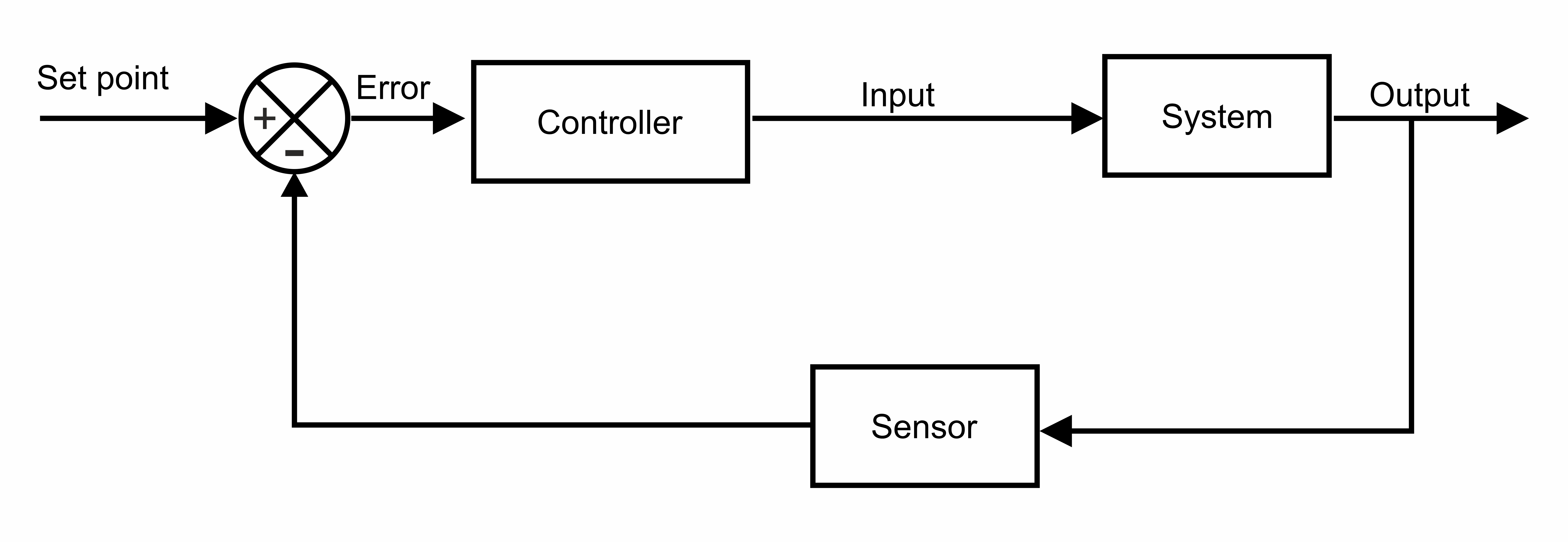
A closed-loop or feedback control is a control system in which the output of a process or system is measured and compared to the desired value for that parameter. The image below shows the general idea. The set point is the desired value for the output of the system. This value is compared to the actual output from the system, which is measured through a sensor, that provides the feedback (hence the name) to the controller. The controller in turn modifies the control inputs in response to the deviation (error) between the desired and measured values for the output.
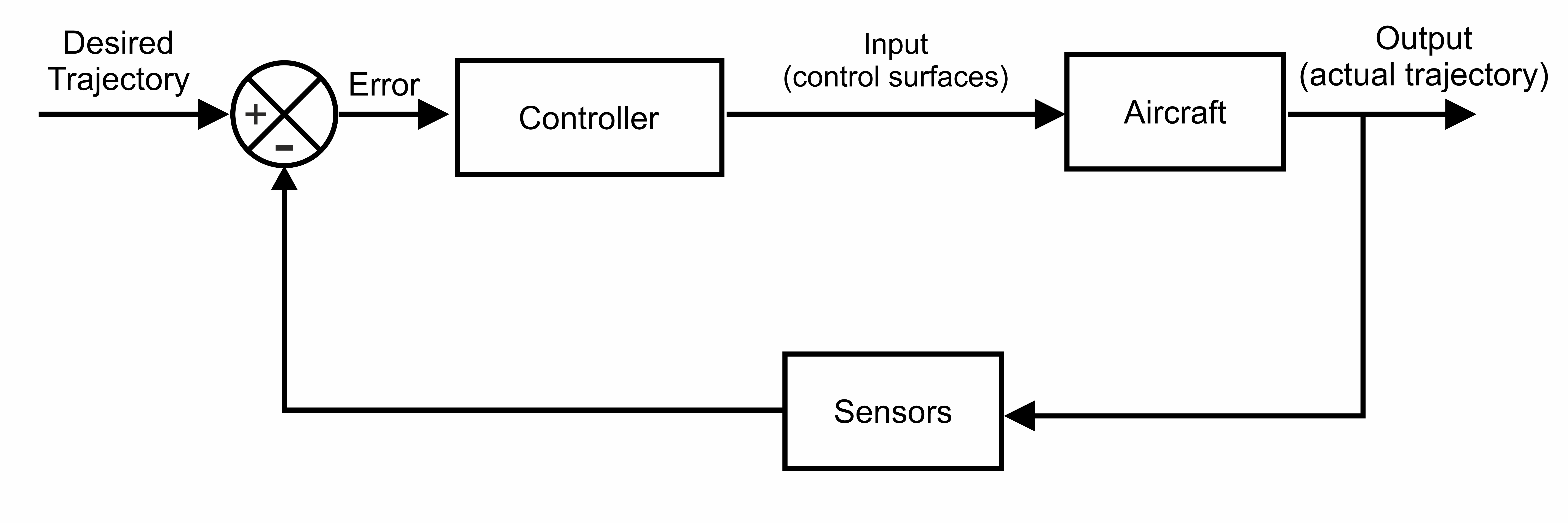
This is a little abstract to understand, so I’ll bring you a more real world example. Below you can see a simplified schematic of the closed-loop control system for an aircraft autopilot, which controls the plane to ensure that the desired trajectory is being followed. The controller will change the position of the control surfaces, such as ailerons, elevator, and rudder, in response to deviations from the desired trajectory. The actual trajectory of the aircraft is measured by sensors (GPS and inertial measurement units), which provide feedback to the controller.
The next example is the direct analogy between race car development (both design and setup) and closed-loop control systems. Here, the “set point” is the desired behavior of the car, which includes many aspects, such as directional stability and control, grip level, cornering balance, straight-line speed, and so on. The feedback from the car behavior comes from two sources, the data acquisition system of the car and the driver. Driver feedback should always be in the loop! In this system, the “controller” is the performance engineer, which will suggest design or setup modifications (the control inputs in this case) in order to improve performance.
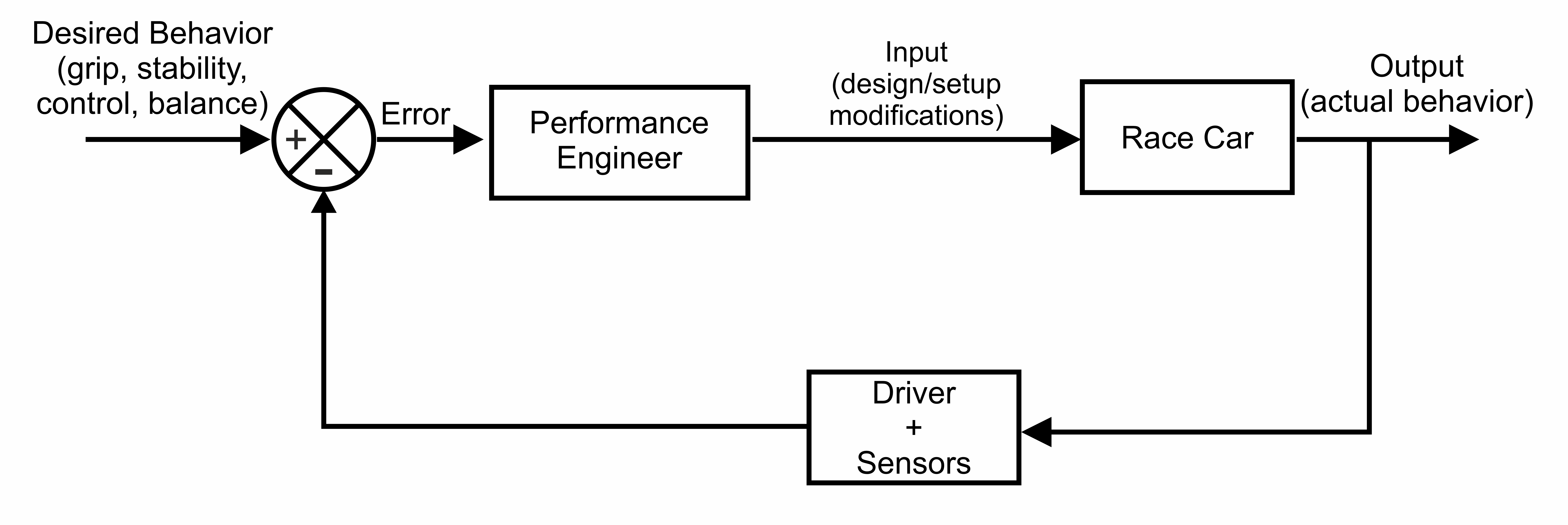
Ideally, the performance engineer should act as a model predictive control system in this case, because he would know how much his modifications would affect the metrics of the behavior of the car, and choose the modifications accordingly. To do that, the engineer should know the trends (what would change) and sensitivities (how much would change), relating the behavior of the car to his setup modifications. This knowledge can only come from reliable, validated models, and careful characterization of the car, which highlights the importance of experimentation and simulation tools.
THE RACE CAR SETUP CYCLE
In many race teams, race car setup is found from trial and error, without a specific procedure. The problem with that approach is that it takes too much track time to find an adequate setup, while in most categories in the world, track time is restricted.
Even in categories without independent testing restrictions, there is the cost related to these tests, and with the high mileage needed to develop the setup without proper guidelines, the cost is even higher, with the extra expense of tires, fuel, brake pads and discs, etc.
Besides, without a technical procedure to develop the setup, there is no consistency in the process, and what works in a given situation does not necessarily apply to all others. Racing is an extremely dynamic environment, where external conditions are always changing. For a race team to succeed, they need to make the right decisions quickly, regardless of the circumstances.
In performance engineering, the behavior of the car is tweaked through a structured process, which involves the creation of performance KPIs (key performance indicators) and the correlation of these indicators with setup parameters. This generates much value to race teams, both in terms of cost and results. This work is done through the cycle below:
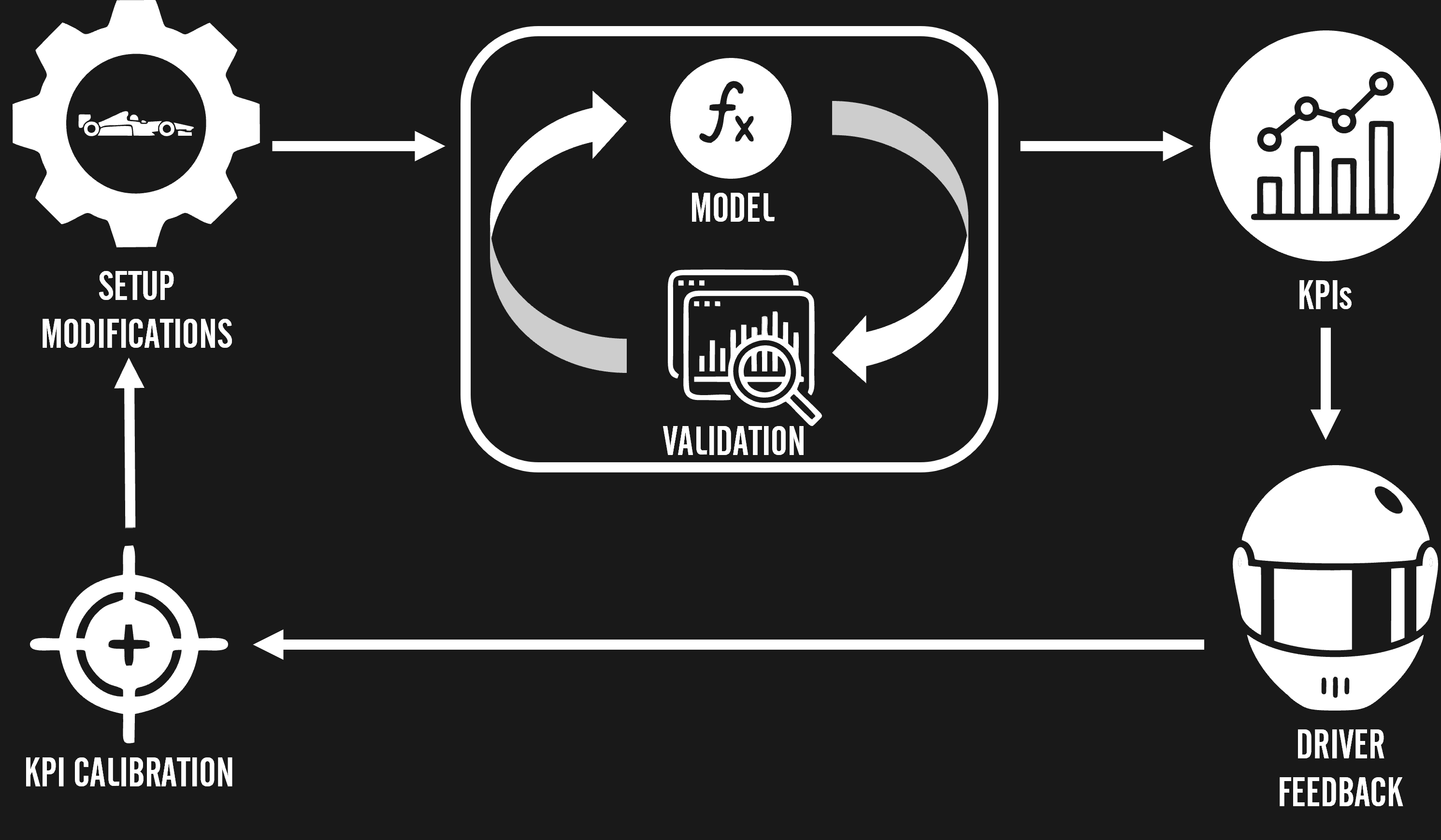
The cycle consists of an internal model/validation loop, where models are developed to predict the behavior of the car. These predictions are tested in the experimental validation step, with tests in the track or rigs, depending on the model being validated. Once the model predictions are proven, the process moves to the next phase. Otherwise, the model is tweaked until its predictions are reliable to an acceptable tolerance.
With the model validated, one can extract KPIs from it. These KPIs serve to quantify specific aspects of the car behavior, such as the presented in the previous section of this article (grip, directional stability and control, balance, etc).
Next, driver feedback is correlated with the KPIs, identifying if a given aspect of the behavior of the car needs to be amplified or attenuated, hence finding out if the value of the KPI should increase or decrease. For example, the applied model generates a KPI for directional stability with a value X. If the driver identifies that the car needs more stability, X should be increased, and the performance engineer should look for setup modifications that would provide that. On the other hand, if the car is too slow in its steering response, the car may be too stable, and therefore, X should be reduced. This process is the KPI calibration.
Finally, with a validated model and KPIs calibrated to the driver style, one seeks setup modifications that will improve performance without harming the conformity of the car behavior to the driver’s style.
The setup cycle presented above is actually a fine tuning of the car upon an established baseline setup. The process for establishing this initial setup is somewhat similar to race car design. One starts with performance evaluation, looking at previous results from the car in the same track and looking at how far you were from the competition (if it is the same time you are visiting a given venue, look at previous results on tracks with similar characteristics).
Based on this data, one establishes performance goals, not only in terms of lap time, but also regarding car behavior. From that, it’s possible to use lap time simulations to choose aerodynamic configuration and gear ratios. With these established, suspension stiffness and damping properties can be selected, and then, an initial configuration for suspension kinematics can be found. Naturally, the process is a lot more complex than shown here, but you can get the general idea.
THE NEXT STEPS
You now got a little taste of what performance engineering looks like. Did you enjoy that? I hope so, because I’m planning a lot of content here in Racing Car Dynamics about this topic. Stay tuned, because I will bring practical examples of simulation and characterization data, so the next posts will be really awesome!
If you don’t wanna miss that, make sure you follow all the channels of Racing Car Dynamics, our Instagram, and our YouTube channel and as usual, our email newsletter (subscription form below). Some of the contents in these channels won’t be available here on the website, so make sure you follow our social media, and you won’t miss anything.
KEEP UP TO DATE