 www.grabcad.com
Race car design is one of the most fascinating and yet one of the most complex aspects of the racing world. The design teams in the many motorsport categories are constantly developing new solutions with one single goal in mind: to make a car that, in combination with the driver, travels the distance of a circuit in an amount of time smaller than any other driver/vehicle combination present in the race venue at the day. But, how is this done?
The design process of a race car (just as many things in engineering) is not a sequential process, but rather one where there are many “backward steps”, as many iterations and solution refinements are made. Before the design process begins, one needs to have full knowledge of the resources available, and on the limitations imposed by these resources. Resources include time, budget, previous experience and resources in the design and building facilities, such as computing power, prototyping and manufacturing machinery, testing equipment, instrumentation, and so on. With cleverness, one or more resources may be substituted by another.
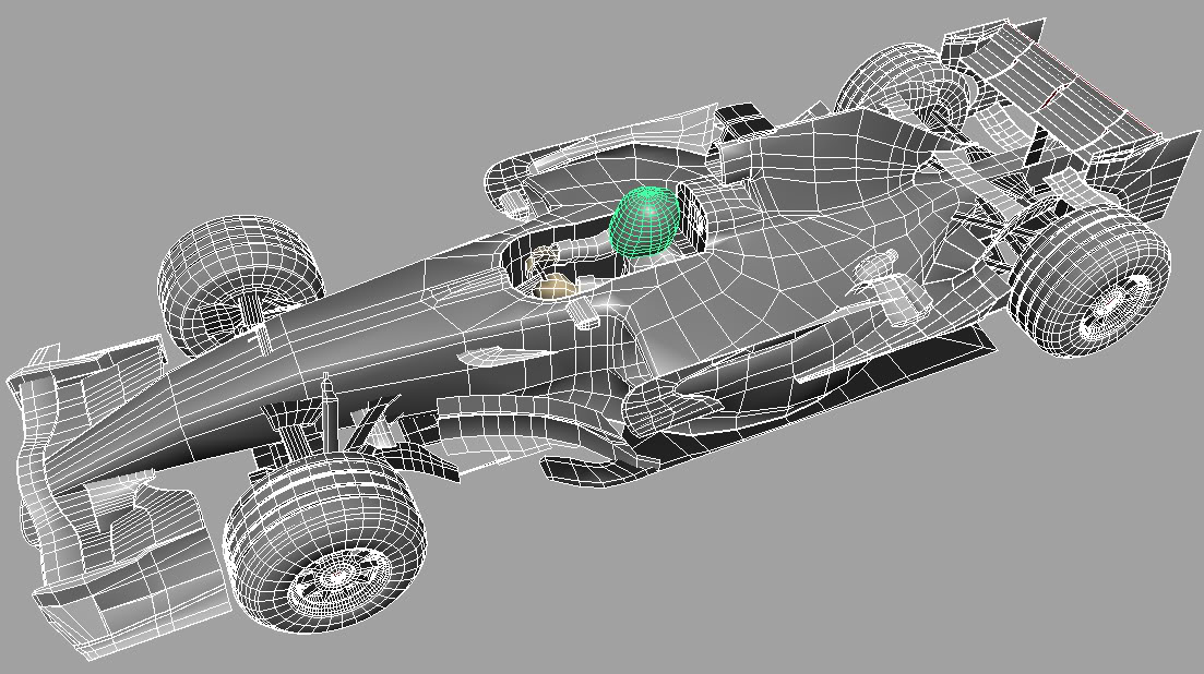
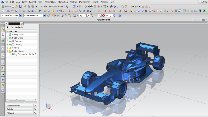
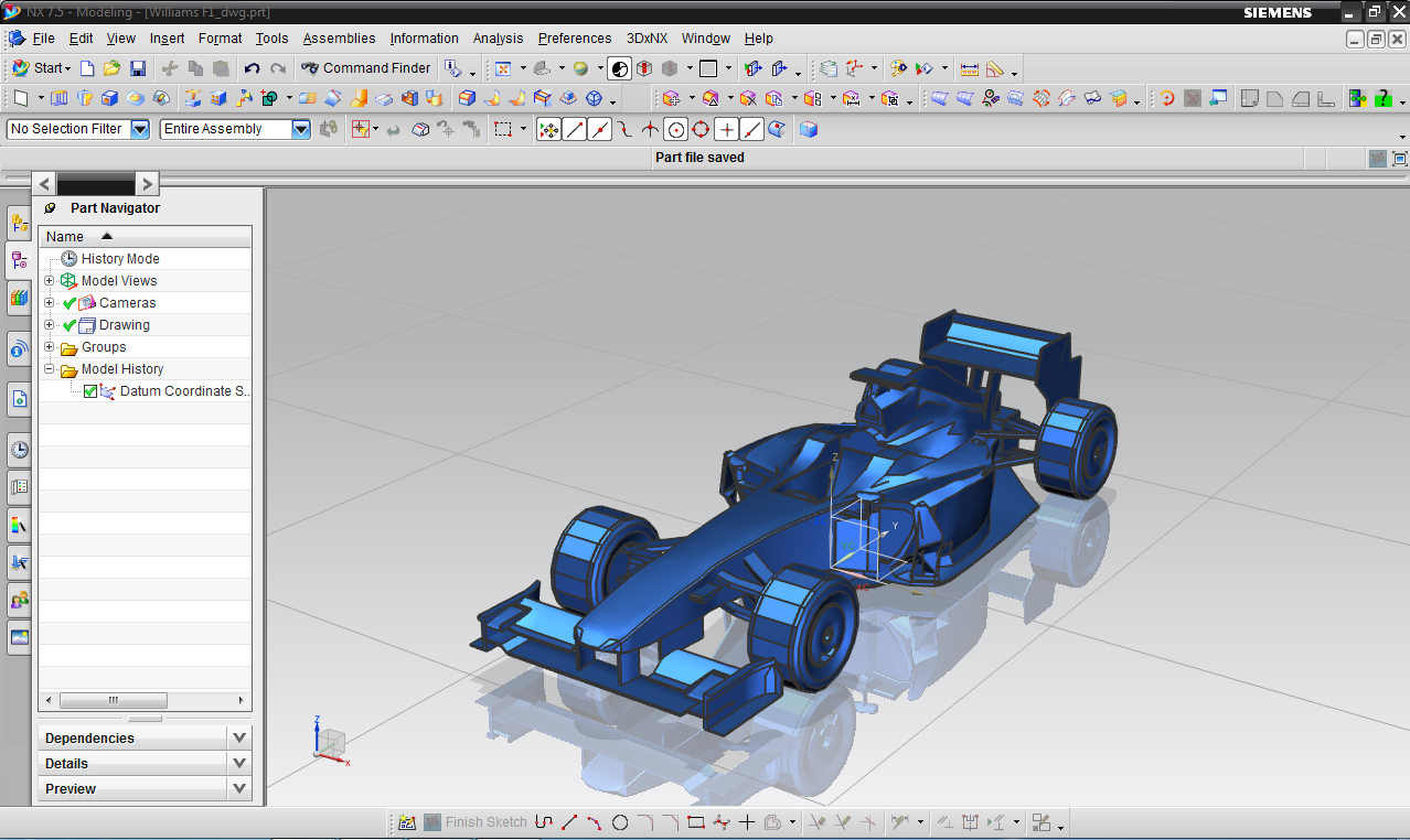
Figure 1. McLaren in wireframe (parkablogs.blogspot.com)
6 Steps to Design Like a Pro
The design approach briefly described here is the result of my previous experience in Baja SAE design team, my internship in the engineering design department of a company that builds racing cars to the largest motorsport category and some minor categories in Brazil, and from some excellent books, which I will recommend in the end of the article.
The approach is made of six steps, namely, Analyses, Constraints and Goals Specification, Preliminary Design, Detailed design, Testing and Development. These steps will normally happen in a non-sequential manner, with some restrictions arising in later steps demanding changes in previous stages.
1. Analyses
During this step, the design team will gather information that will serve as a foundation to set the design constraints and goals. Here, all the regulation changes are reviewed, and their impact on the design is assessed. For example, the refuelling ban implemented in the 2010 Formula One Season, forced teams to run larger fuel tanks, and they also had to take into account the changes on CG height due to fuel burn off. Also, the introduction of restrictions on fuel flow and fuel load per race, in 2014, forced manufacturers to increase their engines efficiency.
Later, a performance analysis is conducted, in order to evaluate the performance of a previous design, if there is one, identifying its strengths and weaknesses. The goal is to recognize the features of the previous car that the engineers should to try to keep for the new design and the ones they should try to eliminate.
Finally, a benchmarking study should be conducted, in order to evaluate the performance of concurrent teams, identifying the gap between one’s own design and that from other teams. Data from opponent teams will generally be extremely difficult to get your hands on, especially in the higher echelons of motorsport. Yet, the design team should do their best to quantify the performance of an opponent, as this is fundamental in specifying the performance goals.
2. Constraints and Goals Specification
At this stage, the design team should look at the constraints imposed on the vehicle. The constraints are the practical limits within which the team should work on. The primary constraints should be the category technical and sports regulations. The designer must be completely aware of these rules and the limitations imposed by them. Also, it might be the case that costs and work force restrictions are imposed either by regulations, or by a limited budget. One good example is the 2-week shutdown that occurs in Formula 1, due to an agreement done by Formula One Teams Association (FOTA) intended to reduce the costs of running a competitive team.
Other type of constraints are those imposed by mechanical parts available. This includes tyres, engines, transmissions, dampers and brakes. Particularly, the tyres are a very important parameter to look at, as they provide the entire controls for the machine. It is said that designing a race car is all about optimizing the use of the tyres. A design team should be aware that in order to be competitive, they must work to the absolute limit of the constraints.
After the design constraints are identified, it is necessary to define the goals, which will guide the whole design process. These could be specified in the form of measurable parameters and should specific enough to allow for design orienting. The goals are related to the following areas:
Performance – this is the most important set of goals in a race car, as its main purpose is to have a higher performance than any other teams’ design. Performance goals should be quantified by several parameters, such as the acceleration capability in all directions (g-g diagram, which will be explained in a later post), top speed, fuel and tyres consumption, cooling requirements and so on.
Figure 2. G-G diagram comparing performance envelopes for a Toyota Celica and a Porsche 928S. The curves represent the combined (longitudinal and lateral) acceleration capability of the cars. (www.temporal.com.au)
Performance goals can also be set in relation to specific systems, as opposed to the whole car. For example, the goals for aerodynamics might include a specific value for the lift/drag ratio, and the location of the center of pressure (CP), while goals for the suspension might include a specific value for roll sensitivity, weight transfer, suspension travel, steer and camber variations and so on.
Handling – The race car should have good enough control capabilities to allow the drive to operate it at the limits of the g-g diagram. This includes specifying details for some control systems such as steering, suspension, and other parameters. There is much more analysis that could be done at this stage toward optimizing the preliminary design.
Structure – This include bending and torsional stiffness, together with local strengths required to cope with maximum loads from braking, accelerating, side force, hitting kerbs, aerodynamic loads, engine torque reaction, and so on. It is now common practice in almost all levels of motorsport to use finite element analysis to allow these goals to be achieved, specially where there are rules imposing crash tests for chassis homologations.
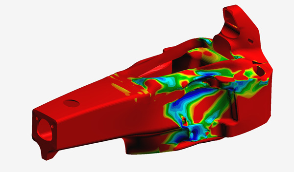
Figure 3. Finite Element Analysis of a Red Bull Formula 1 chassis (www.racecar-engineering.com)
Driver Accommodation and Safety – The cockpit must provide enough room for the driver, with comfortable seats and restraints, adequate temperature and vision of the track good enough to allow the control of the car at performance limit operation. In addition, a responsible design should use the best available in safety equipment, such as fire equipment, rollover and crash protection, and so on.
Adjustable Features – Some features of the car must be adjustable, in order to provide setup options of the car, allowing the vehicle to be adapted to different circuits. Typical setup capabilities include weight distributions through movable ballast and adjustable wheelbases, aerodynamic changes through wings (either different wings or wing settings) and suspension adjustments (vehicle attitude and ride height), and suspension adjustments such as wheel loads (through springs and anti-roll bars), damping, static settings (toe and camber), geometry (variable swing arm length or roll center heights) and others.
3. Preliminary Design
The goal of the preliminary design is to define general arrangement of components in the car. Here the designers should satisfy the packaging requirements and other specifications such as CG location for weight distribution and balance requirements for handling. Depending on the aerodynamic levels allowed by regulations, the aerodynamics might determine much of the package outline, especially in what concerns ground effect vehicles.
At this stage, some data gathering must be done in order to distribute components properly around the car. If real data is not available, the design team should estimate it. The most important information here is the size and weight of components. This is used to make a rough layout of components location, and from that to make an estimative of overall weight and CG location.
The desired CG location will generally depend on neutral steer points (which depends on the choice of tyres), the location of the aerodynamic center of pressure (CP), required load on driven wheels for traction and required load on steering wheels for control. In addition, the CG must be as low as possible, to reduce lateral transfer on the car.
So far, we have just gathered relevant information and analysed that information in order to decide which path to follow. The drawing of some important views sketches in a CAD software gives start to the design process itself.
The approach that I use is to start a 3D sketch and work at it in 2D, choosing relevant plans to draw. It begins by the choice of tyres and wheels, which by themselves define the hub locations. Relevant dimensions of the car must be defined before drawing process begins.
The wheelbase and track dimensions must now be chosen. Wheelbase affects longitudinal load transfer, weight distribution, polar moment of inertia and yaw response of the car, during transient manoeuvring. In summary, a longer wheelbase will reduce longitudinal load transfer, and provide higher yaw damping (and hence more stability) at the expense of a smaller yaw response (the car “points into” the corner in a slower fashion). As with everything in design, a compromise must be adopted.
Track widths on the other hand, affects lateral load transfer, and in case of closed wheel race cars such as sports cars and sports prototypes, frontal area of the car (and hence, aerodynamic drag). Since drag is generally of low concern in motorsports development (except in categories with limited power engines), it is preferred to have track width as large as possible, since it reduces lateral load transfer.
With tracks and wheelbase defined, it is time to define roll center heights. As you saw on the previous article about lateral weight transfer, roll center heights directly affect lateral weight transfer, and hence, should be kept as low as possible. Commonly, the obstacles to achieve this are limitations on camber variation due to the suspension (this will be explained in a future post about suspension geometry), but, in off-road vehicles ground clearance limitations may also make any attempt to lower roll centers more difficult.
At this point, upright geometry is defined. If a market component is to be used, its choice automatically defines its points. If a custom-made part is chosen instead, concerns about the steering geometry such as caster and kingpin angles, and steering moment arms such as scrub radius, spindle length and mechanical trail and steering offset. Many compromises are present here and the detailed discussion of steering geometry is out of the scope of this post, but the subject will be addressed in a future post.
Now, the 3D sketch is divided in front, rear, side and top view sketches. On the front and rear sketches, roll centers are drawn, along with the upright points. Since double A-arm suspensions are now standard in racing, I will consider it as the only option worth to analyse in this brief discussion. Also, the relation between spring travel and wheel travel (installation ratio) is chosen, and a brief layout of suspension arms is defined, allowing an estimation of the location of suspension pick-up points.
On the side view sketch, front and rear axle centrelines are drawn together with the ground line and the undertray line, thus defining the ground clearance of the car. On the top view, a rough estimation of the location of major components such as engine, gearbox, fuel, water and oil tanks, radiators, seats, and minor components, such as pedals, gear lever, pipes an throttle cable is made.
We now choose the chassis type. In most racing environments, either a space frame or a carbon fibre unitary construction should be used. Carbon “tubs” as they are called, provide much higher strength and stiffness with a remarkably low weight, but the exorbitant costs inherent to this type of chassis limit their application to the highest echelons of motorsport. The specifications shown here will be pretty similar for either type. Categories based on road cars will often have the original metal unitary construction reinforced with a space frame-like roll cage.
The chassis design begins by specifying the location of the bulkheads, which are the major transverse sections of the chassis. In general practice, there are four bulkheads, namely, front, first intermediate, second intermediate and rear. The actual location of the bulkheads is dependent upon if the car is to be front- or rear-engined.
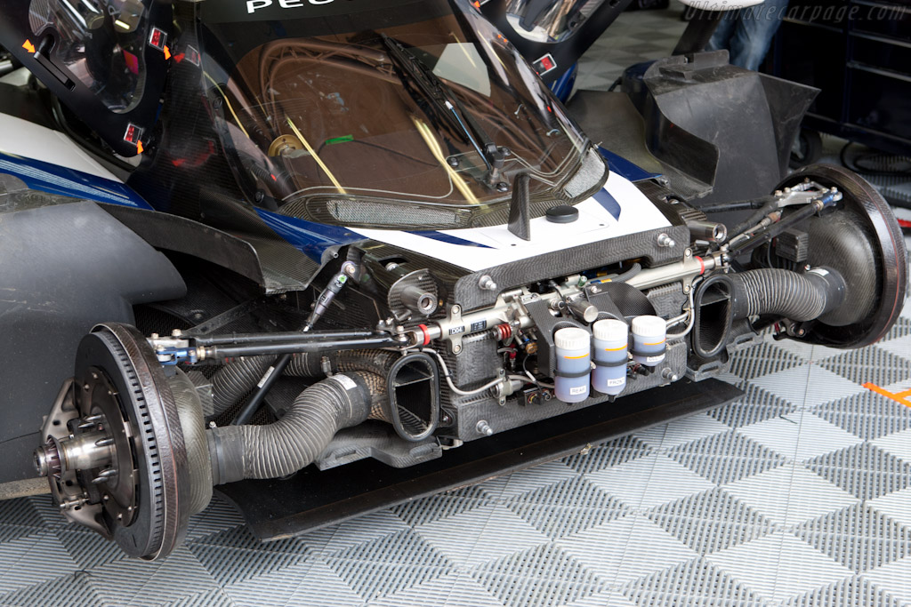
Figure 4. Peugeot 908 HDi FAP LMP1 front bulkhead. Notice the steering gear and hydraulic reservoirs for the brake (two at the left) and clutch (right) master cylinders. (www.ultimatecarpage.com)
Since here in Racing Car Dynamics I will only address the design of rear mid-engined cars, I will focus on this type of layout. Front and rear bulkheads will basically have the same function in both layouts, but the intermediate bulkheads will have different purposes. Each pair of consecutive bulkheads forms a bay. On rear mid-engined cars, the front bay will be occupied by the driver’s legs and feet, the centre bay will receive the seat (or seats) and in the rear bay the engine and/or transmission are placed. Ideally, the loads from the suspension should be transmitted through the nearest bulkhead, but in the case of the front bulkhead, this component should also serve as a support for steering gear, pedals and brake and clutch master cylinders.
The next step is to sketch a member to support steering wheel and instruments. This member should form a bulkhead between front and centre bays. The driver opening in the cockpit is then defined. If the chassis is a space frame, different forms of triangulation need to be found, since the legs of the driver will pass through this bulkhead. At this point, it is helpful to draw a rough sketch of the driver, in order to avoid driver packaging problems on a later design phase.
It is possible to use the entire power unit as a structural member, provided that the mountings are stiff and strong enough. This is a very common practice in formula racing and in high levels of prototype racing. In general, front mountings for the engine are located on the side frames, and this might involve the use of long mounting bars on a two-seater. The car produced for Brazilian Stock Car in the company where I did my internship used this solution to engine mounting (the car was front mid-engined).
Since one of the primary purposes of the chassis is to take bending loads, all transverse bulkheads should be part of a structure strong enough to support itself with negligible deflection in bending. A successful chassis design is one that combines this with adequate torsional stiffness. Basically, tubes designed to provide bending stiffness should also be placed in positions to deliver torsional stiffness.
A reminder should be made to take into account driver’s seat, feet, knees, sight line and steering wheel position while working out the basic layout of the car. This can always change as the design progresses, but by now, it is possible to have a pretty good idea of the general layout of the chassis, in the form of a series of bulkheads.
Longitudinal members are then used to support these bulkheads. The quadrangles formed by the longitudinal members and bulkheads should be triangulated whenever possible taking into account access for possible maintenance or access to pit crew. The overall body shape of the car is now defined as series of transverse and longitudinal sections, into all the components will fit without any need for external alterations. Figure 5 shows the preliminary design of a motorcycle-engined race car, in a pretty advanced stage, as demonstrated by the advanced modelling of some components.

Figure 5. Preliminary design of a motorcycle-engined race car. (www.cardesignersandbuilders.com)
At this stage, some planning for aerodynamic development and overall body shape may be considered. Some CFD analysis and scale-models wind tunnels tests may be run in order to proof initial concepts that will be later developed during the detailed design stage.
After all this process, the 3D drawings of major and some minor components are incorporated to the design, with their weight and size being reasonably well-estimated. This should provide a mock-up for overall arrangement of components, and it can be used to check for interferences and complement the drawing process. If real components CAD drawing are available, they should be used. At this point, a good idea of overall weight distribution of the car can be estimated, and if needed, adjustments can be made to the preliminary design. The design team will now be able to begin the detailed design.
4. Detailed Design
In the beginning of this stage, a lot of information will be available from the preliminary design. This information should be confronted with the design goals. Examples of data available from the preliminary design include the ones below:
• Overall dimensions, components locations and packaging;
• Power curve from engine manufacturer;
• Tyre data from supplier;
• Body shape from preliminary CFD simulations and wind tunnel testing;
• Weight distribution and CG location, and adjustment ranges.
At this point, individual parts will begin to be designed. The first step is to incorporate a Failure Modes and Effects Analysis (FMEA) to the component design. In this analysis, several failure modes for a part (or system) are listed, and the design team should arbitrate values to quantify the probability of a specific failure mode to occur, the chance of it being detected and the severity of that particular failure mode (failure consequences). These three parameters will be reflected in a score that represents how relevant a particular failure mode will be, helping to identify in which failures the design team should expend more energy.
The detailed design process includes constant solution proposal to specific problems and analysis of these solutions. These efforts should be run in parallel, since data from one is required to conclude the other. The proposal of new solutions might follow the engineering design process, which consists of the following steps:
1. Identify the problem
2. Identify criteria and constraints
3. Do a background research
4. Brainstorm possible solutions
5. Analyse the proposed solutions
6. Identify the best solutions
7. Prototype and test the chosen solutions
8. Communicate the solutions
9. Refine
Now, construction of a wind tunnel model is an early priority, and CFD analyses are now run with a much deeper level of details incorporated. Other systems are also designed in a more in-depth look. For the suspension, tree-dimensional pick-up points are located, along with steering geometry drawing. From this information, kinematic analyses of the suspension are run, aiming to evaluate how the geometry will vary during the different operational conditions.
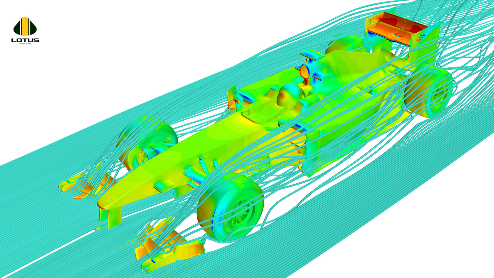
Figure 6. CFD analysis of a Formula 1 car. (tecnicaf1.files.wordpress.com)
If no kinematic problems are found, suspension stiffnesses (spring and anti-roll bars rates and installation ratio) should be defined. Many approaches are available to do this. One can restrict suspension displacements under specified load conditions, or use suspension stiffnesses to alter lateral weight transfer distribution to give desired understeer/oversteer balance or one can choose a suspension stiffness that would give a specified working frequency (this should be worked together with dampers).
Other detailed design efforts include cockpit layout, with seats, restraints and controls being located and detail designed. Engine mountings are drawn and stress-simulation along with prototypes building, to allow stress tests, are carried. Radiators, fuel, water and oil tanks are also detailed designed, and the same is done to the remaining components and systems.
For the design of the components, stress analyses through finite elements should always be conducted, especially to assess fatigue strength of components. For this, a good knowledge of experienced loads is crucial. The computational simulations should precede the building of prototypes to validate the results obtained. Some components will be design for stiffness rather than strength.
During the detailed design, analytical tools are available to the designer. Useful programs may be made in-house requiring almost zero computational resources. This can be used to determine suspension geometry and stiffness; simples stress analysis and performance simulations.
At this point, complex models to evaluate the many performance parameters are introduced, and this is the first time the designer will have a good vision of how close the car is to the design goals. If the performance is not as desired, or if design conflicts arise, returning to a previous design phase is necessary.
5. Testing
Testing is the most crucial aspect of a race car’s design. A great design effort might be lost if not enough tests are carried. Some categories, such as Formula 1, impose restrictions on off-season tests, aiming to reduce costs. This leaves only the specified pre-season tests and the free practices for the engineers to work on the cars.
Pre-season tests are generally a series of events with one week of duration each. The goal for the pre-season testing is to confirm that mechanical and aerodynamic behaviour of the car is as planned during the design. Also, the reliability of the components and structures is assessed and possible problems in the systems are identified.
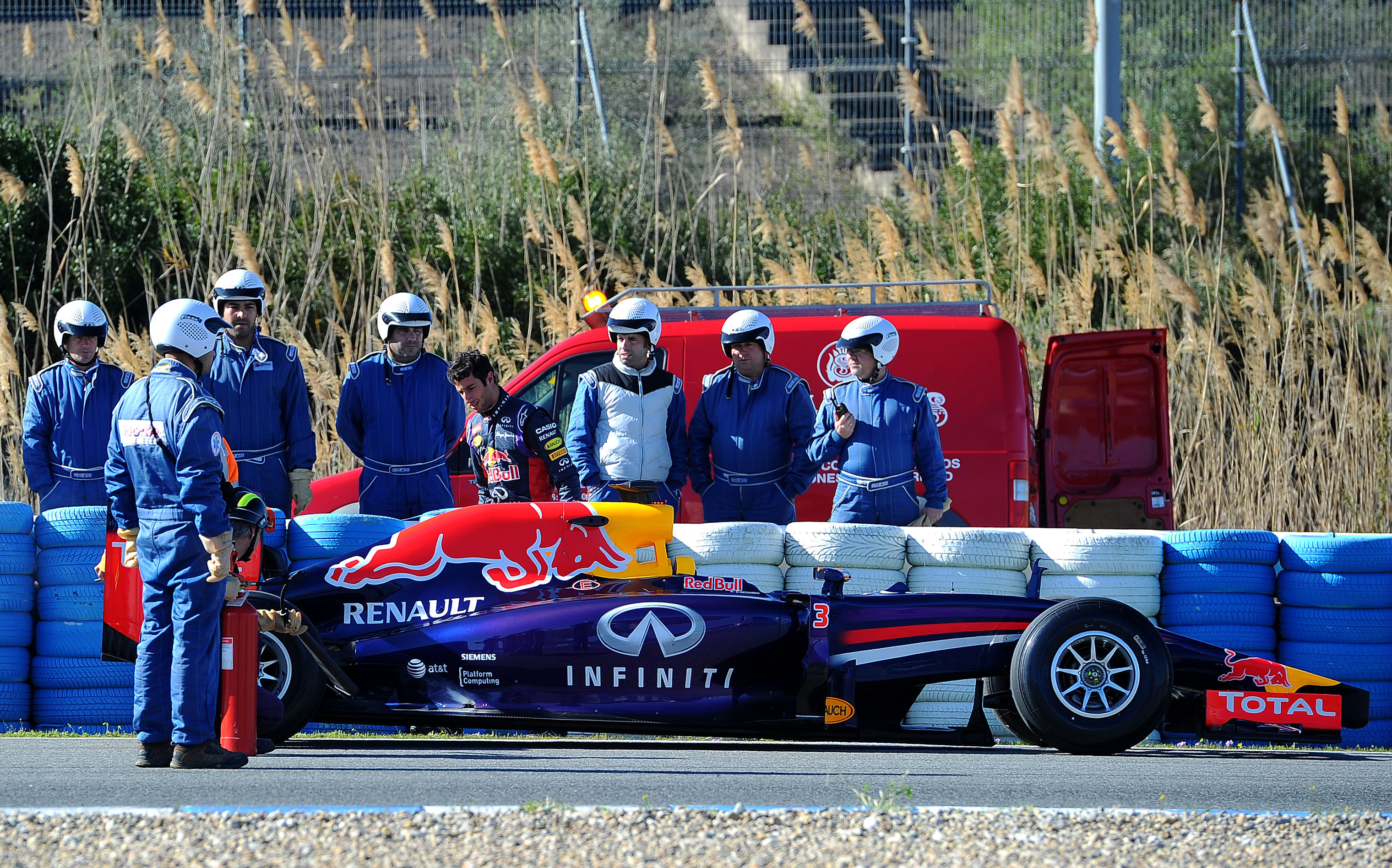
Figure 7. Testing allows to identify reliability issues. (metrouk2.files.wordpress.com)
The most important outputs from testing are data logging and driver feedback. Data logging allows the engineers to assess values from parameters of interest, while driver feedback provides the response on how the car feels.
Tests are also run on free practice sessions of a race weekend, but in this case, the amount of time available to test is much reduced. During these sessions, the car must comply entirely with the rules, and this restricts the testing of any radical components. Generally the test of new components and evaluation work is done during the Friday morning session, as in most cases, teams will be concentrating on car set-up and race strategy work during the afternoon session and Saturday morning session.
6. Development
The development stage of a race car during the season is one of the most demanding aspects of race car engineering. Updates must be developed for each race, in a minimum amount of time. They also need to cope with other teams’ improvements, in order to allow the creation of the most competitive package.
The development of new components are generally timed, such as to not cause any logistics problem. For example, in Formula 1, the development of a new bodywork is arranged so to not coincide with a ‘flyaway’ race (a race run outside of Europe). Generally, there are limitations on the number of parts that will receive new development, since the factory can manufacture a limited amount of parts. Hence, the engineers must weigh up the magnitude of the possible gain against the practical difficulty of achieving it.
A brief description of the development process is as follows:
• Conception – After the briefing with the race engineer on the required changes after the last race, the design team arrives at a new concept , or a worthwhile modification to an existing component.
• CAD modelling – A CAD model is drawn for the concept part.
• CFD/Wind tunnel evaluation – The concept is analysed using CFD and/or wind-tunnel testing to evaluate its potential benefits.
• Composite design – The composites department designs tooling, mouldings, jigs and fixtures required for bonding and assembly, and any documentation required.
• Manufacture – might be done in-house or by external suppliers.
• Design Verification Process – Structural verification of the component including proof, fatigue testing and legality checks.
Now you have an overview on how high level motorsport teams or companies design their race cars. As a student willing to learn more and more about the racing world, I intend to share a lot of material about the process of designing a race car. If you don’t want to miss that, please subscribe to our list below. See ya!
 KEEP UP TO DATE