www.f30driver.com
Now that you already know the fundamentals of motorsport data acquisition and why use it, let’s have a more in-depth look on the subject. In this post, I will talk about data acquisition system (DAS) hardware. This is the actual tool the engineer has to collect information on the car.
The DAS hardware consists basically of a logging unit, sensors, display (not mandatory, but very common), all the wiring that connects the system together and an output device (either a computer or a laptop). It works like that: the sensors interact somehow with the physical parameter being measured (this will be further explained later in this post), and transform it into electronic signals, which are transmitted to the data logging unit through the wiring in the system. The data logging unit then interprets the electronic signals by comparing them to its stored calibrations. Finally, it calculates and records a value for the physical parameter.
An external link is used to enable communication between the system and the output device. This is generally a two-way communication, as some data logging units allow the user to set some parameters for the DAS. A display may be connected to the system via another communication link in order to show some readings to the driver. In some DASs, dashboard and logger will be integrated in one component.
Component Location

Component location must be carefully thought. (www.npsaracing.com)
In order for the DAS to work properly, the data engineer or the person responsible for installing the DAS in the car has to make sure that no faulty installation that can interfere with the functionality of the system will occur.
The logging unit must be protected from external environment influences, such as weather conditions. Hence, it must be installed inside the cockpit, away from moving or hot parts or otherwise parts that could electromagnetically interfere with the electronic signals (for example, motor-generator units in hybrid cars cables, or ignition coils or related wiring).
Sensors need to be close to where the measures will be made, and in some cases, that may mean that the sensor will be dangerously close to a moving part. Extra care is necessary in order to make sure the sensors will never get in contact with the moving parts to which they are close.
The wiring that connects the system must be carefully routed and fastened. They must not to be taut, otherwise they can get disconnected from the DAS due to the forces originated by mechanical vibrations (vibration is a product with plentiful stock on a racing car).
Special care must be taken with accelerometers. They must be as close to the centre of gravity (CG) of the car as possible, otherwise they will tend to give biased readings (more on that later in this post). Also, they must be in a stiff, vibration-isolated support, otherwise, a lot of “noise” from vibration will arise.
Data Logging Unit
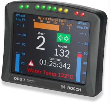
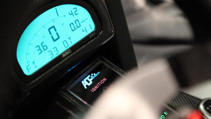
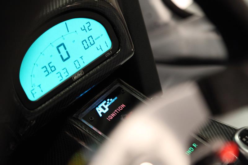
Bosch display with integrated logging unit. (www.bosch-motorsport.de)
Where you will install your data logging unit depends on whether it is integrated with a display or it is a separated unit. In the former case, you should obviously place it in a visible place to the driver such as on the dash panel or on the steering wheel. In the latter, the logging unit should be placed as low on the car and as closer to the centre of the car as possible to improve the weight distribution (loggers are not that heavy, but every bit counts) and in a place far from other electrical and electronic components, perhaps on resistant brackets to avoid at least some vibration.
The engine-related parameters must be measured and logged by the electronic control unit (or engine control unit, ECU) in order for the engine to work. Most engine ECUs offer the possibility of connection to a logging unit to transfer engine-related parameters.
Now, let’s take a look on the most common types of sensors, beginning with the basic speed sensor.
Speed Sensors

Wheel speed sensor and trigger wheel (the X-shaped wheel in the center). (www.veracitydata.com)
As you further read the posts on Racing Car Dynamics about data acquisition, you will learn that speed is one of the simplest, yet one of the most important parameters to look at. The most common type of sensor is a magnetic pickup which generates electrical pulses every time a magnet (trigger), installed typically on the wheel, passes by the sensor. Also, a ferrous component of the car, such as a wheel bolt head or a toothed wheel, can be used instead of the magnet. The same type of sensor can be used to measure rotational speeds, and thus are used for engine RPM, turbocharger shaft speed and so on.
The sensor is generally gap sensitive, and this must be carefully taken into account when installing it. The sensor is mounted in a bracket attached to the wheel hub. The required sensor-to-trigger gap may vary from fractions of a millimetre to perhaps one or two millimetres, depending on the specification of the sensor, and thus, the brackets must be sufficiently rigid to avoid collision that would ruin the sensor.
In the high echelons of motorsport, a speed sensor is installed for each wheel. That can provide a lot of useful information about a car’s handling. However, in the entry levels of motorsport, generally teams do not have the budget to buy expensive multichannel loggers, and thus only one speed channel is logged. On other series, the use of multiple speed channels is forbidden to avoid the installation of traction control systems (more on that on a later post). But in which wheel should you install your sensor?
Well, some people agree that it is better to install it on a driven wheel, helping to identify traction loss problems. However, Simon McBeath in his book Competition Car Data Logging prefers to install it on a non-driven wheel to avoid the risk of losing meaningful data and suggests that traction loss can be easily identified by comparing RPM data with non-driven wheel speed data. Jörge Segers in his book Analysis Techniques for Racecar Data Acquisition, also suggests that when only one wheel speed channel is available, it must be measured at a non-driven wheel, and the speed of the driven wheels can be calculated from engine RPM and gear ratios.
With any option, there is always the possibility of a lock-up on the wheel, due to excessive braking loads. The recommendation is then to install the sensor on the wheel that will be on the outside of the corner in most part of the track. The higher vertical loads on the outside tyres will reduce the chances of a lock-up to occur.
Another sensor used to measure speed is the Correvit Optical Sensor. It basically is an optical sensor, which measure the relative velocity between the vehicle and the ground. In Formula One, it is used together with a pitot tube (airspeed sensor) to measure the head or tail wind speed, among other things. It is better explained on this video from Sauber F1 series “Cutaway Insights” (which I totally recommend, by the way).
Cutaway Insights – Episode 10: Correvit Optical Sensor – Sauber F1 Team
Accelerometers
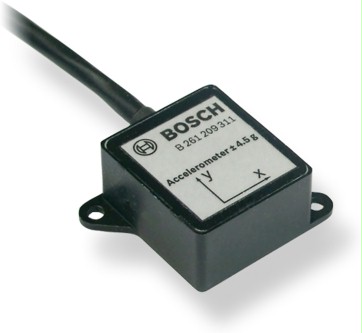
Biaxial Accelerometer (the axis in the tag indicate how the sensor should be aligned.
(www.bosch-motorsport.de)
This type of sensor can be used to measure either accelerations or forces, by multiplying the measured acceleration by the sum of the masses of car and driver. The most common application in racing is to measure cornering and acceleration/braking forces, or equivalently, lateral and longitudinal forces. They can be a single axis, biaxial or triaxial, which means in how many axis they can measure accelerations. Instead of a triaxial sensor, two or three single axis aligned in different directions may be used.
The sensor consists of a small mass that is free to move along one axis (for single axis accelerometers). The mass is mounted on deflectable beams, and when the sensor suffers acceleration in the direction of allowed movement, mass moves and compresses the beams. Then, strain gauges measure the deflection of the beams and converts it to an electronic signal.
The accelerations or forces of interest are given in terms of a fraction of the gravitational acceleration (9.81 m/s²) or the gravitational force. The calibration of this sensor can be done using only two points. First, the sensor is left at rest, which represents the zero value. The sensor is then positioned in a way that will align the measurement axis direction with the gravity actuation axis, which is equal to 1 G.
For the calibration the car should be obviously put in a level surface. The accelerometer must be installed with the relevant axis of the car. As said before, the accelerometers should be installed as close as possible to the vehicle’s centre of gravity. If this is not done, the sensor will read biased values. For example, if the accelerometers are mounted away from the CG, they will record erred values due to either yaw, pitch or roll accelerations (technically, the car spins around points that are not coincident with the CG, but since all inertial forces act on the CG, there will be no moments on this point).
Another potential cause of error is the presence of vibration. It is recommended that the accelerometers are installed on a rigid mount over an anti-vibration material, though using industrial Velcro is said to be satisfactory.
Position or Displacement Sensors
This type of sensors have a huge amount of applications on motorsport. They can measure linear or angular position or displacement. Rotational types could be used to measure steering wheel angle, throttle position (being installed either on the pedal or throttle spindle), brake position, gear selection and so on.

Steering angle sensor (notice the rubber belt used to transmit the rotation of the steering column to the potentiometer). (www.advantagemotorsports.com)
Linear sensors on the other hand could be used to measure damper displacement or throttle position (when installed on the end of the pedal or on the throttle cable end, or on a throttle slide arrangement). Both, linear and rotational position sensors are generally potentiometers, devices that change their electrical resistance with the position of the slider contact (wiper). Once the sensor is calibrated, it will return an angle or distance in relation to the zero position.
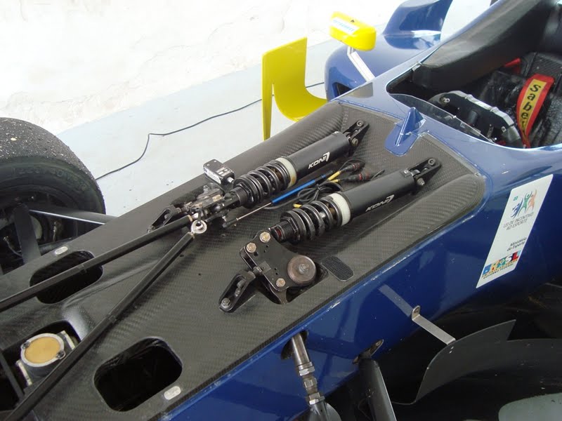
Linear potentiometer used to measure the displacement of a Formula Three damper (the blue rod between the dampers is the sensor).
Another type of position sensor is a variable differential transformer, which could be linear (LVDT) or rotational (RVDT). They work through electromagnetic principles by which variable voltages are generated in the inducted coils due to the movement of a magnetic core. The typical applications are the measurement of damper displacement or brake pad and brake disc wear, since the sensor can accurately measure long strokes as well as few millimetres movements.
Temperature Sensors
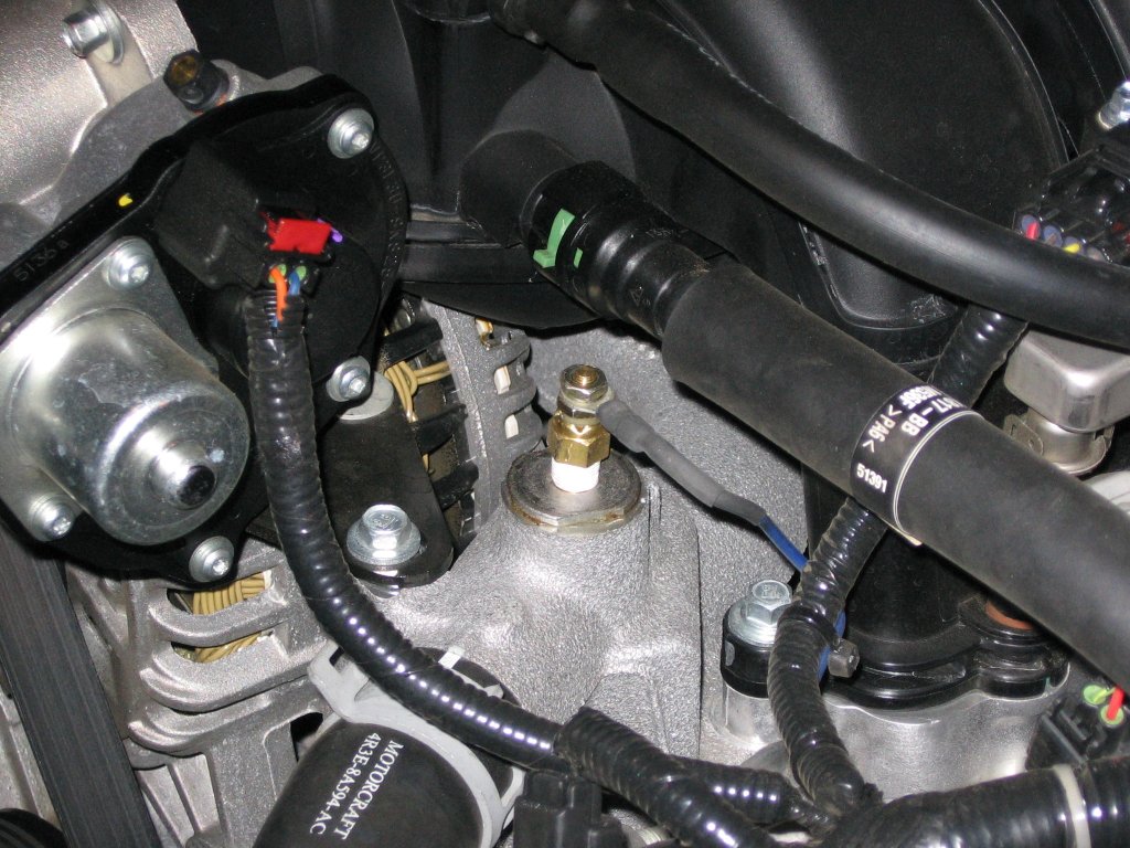
Water temperature sensor in a Ford Mustang. (themustangsource.com)
This sensors can be used in several applications in a race-car. Starting with engine-related parameters, it could measure the temperatures of liquids like water or oil, the inlet air going to the engine, the hot gases from the exhaust, brake discs, tyres and so on.
They may be contact sensors like thermocouples (two different conductors in contact at one or more ends that generate voltage whenever the temperature of one of the contact spots is different from a reference temperature in other parts of the circuit) and resistance temperature detectors (conductors whose resistance varies with temperature), or non-contact like infrared sensors.
Non-contact sensors must be used to measure the temperature of moving parts, like the brake discs or the tyres. Generally, an array of sensors is used in each tyre to measure its temperature across different regions, and then record a profile temperature of the tyres. It can be useful to analyse the behaviour of the tyre and suspension (and it can show how well your driver is taking care of the tyres) or to keep an eye on the reliability and safety side, avoiding deflating and overheating (obviously this is only possible when there is a telemetry system, and hence is only common in high levels of the sport).
Pressure Sensors
These sensors can be used to measure pressures of a large range of parameters, like airbox, turbocharger or supercharger boost, fuel, oil and actuators hydraulic fluids or in hydraulic circuits like the brakes. Obviously, this requires different pressure ranges which can be as low as 172 KPa in the case of airbox, or as high as 21 MPa for hydraulic lines.
Different principles may be used to measure pressure, one of them being the diaphragm. It consists a diaphragm with strain gauges bonded at it. When there is pressure on the diaphragm, the strain gauges give a proportional electrical output change, which is read by the logging unit. Other way is a piezoelectric sensor, where electricity is generated by some materials when they suffer a pressure.
Aerodynamics Sensors
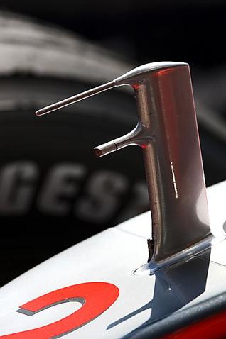
Pitot tube in a McLaren Formula One car. (www.stopandgo.clubf1.es)
Sensors used in aerodynamics have two applications: low range pressure sessions or local airspeed sensors. This can be used to get a profile of the flow around the vehicle and understand better how it is behaving. The pressures of the air around a race car, even though creating massive amounts of downforce, are really low, typically in the range of 7 to 14 KPa. For this, piezoelectric sensors are sufficient to measure the required pressures.
Local airspeeds are generally measured through a pitot tube. A pitot tube is a pair of tubes (that might be concentric or not), with one of them pointing straight to the airflow and the other, called static port, closed in the direction of flow, but open in direction of atmospheric pressure, measuring the static pressure. By subtracting the static pressure from the total pressure (measured by the tube pointing to the flow direction), the dynamic pressure is obtained, and from it, airspeed (the relative speed between the car and the air) is calculated.
Future posts on this section of Racing Car Dynamics will show you how data collected during runs on some circuits will look like, and how you should interpret them. If you want to read more about this, please subscribe to our email newsletter below. Please, don’t forget to say what you think of this article, on the comments below! See you on the next post! 🙂
 KEEP UP TO DATE