

CTV News
Let’s say that you are a race engineer and your driver is having trouble to go around the slowest corners on the circuit. In a brief feedback after the first outing (a set of laps in a session) of the free practice session, the driver complains about excessive oversteer in these parts of the circuit. What would you do, in order to solve the problem?
Well, a thousand changes to the car could be applied. The fact that the problem occurs in the slowest bits of the circuit might rule out the possibility of aerodynamic changes as a solution. Then, most of the solutions available will be related to the subject of this post: lateral load transfer.
Lateral load transfer or lateral weight transfer, is the amount of change on the vertical loads of the tyres due to the lateral acceleration imposed on the centre of gravity (CG) of the car. In other words, it is the amount  by which vertical load is increased on the outer tyres and reduced from the inner tyres when the car is cornering.
The total lateral load transfer on the car can be calculated from its free body diagram, as shown in figure 1. In the image, the car is looked from the rear in a right hand turn. Here,  is the lateral acceleration in G units,
  is the weight of the car,
  is the CG height,
  is the track width and
  and
and  are the vertical loads on the left and right tyres, respectively.
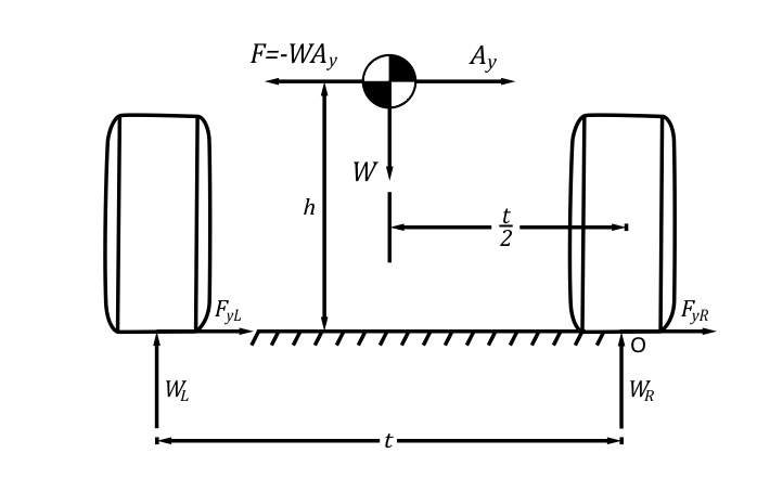
Figure 1. Free body diagram of a car, rear view. (MILLIKEN & MILLIKEN, Race Car Vehicle Dynamics – Adapted)
Taking the moment equilibrium about the point O, of the tyre, we can see that:
Dividing the equation by t on both sides, we obtain:
But assuming a symmetric weight distribution,  , since the left tyre is the outside tyre. Hence:
This is the total lateral load transfer on the car. One important thing to notice is that it’s difficult to change total lateral load transfer by setup. Some setup changes might apply, for example, CG might be lowered by reducing ride height, and track width might be increased by changing wheel offsets properly or using wheel hub spacers. However, these approaches are limited, ride height being affected by the possibility of bottoming out and track width by regulations that place a cap on vehicle width.
But if total lateral load transfer is difficult to change once the car has been designed and built, then how can it be used to improve handling? The secret to answer this question is to focus not on total lateral weight transfer on the car, but instead, on how it is distributed between front and rear tracks. Before I explain this, let me talk about a good thing to understand the subject – the steady-state analysis of a pair of tyres.
Steady-State Pair Analysis
Formula 1 Dictionary
In the previous post about understeer and oversteer, we have addressed the vehicle as the bicycle model, with its tracks compressed to a single tyre. Let us expand that analysis by looking at the pair of tyres. This analysis may even be used to prepare tyre data, in order to make the bicycle model more realistic.
In a pair analysis, steady-state lateral force is obtained for the tyres on a track (front or rear pair), through data from a single tyre. It may be a more practical way to assess vehicle handling in comparison to computer modelling, since the goal is generally to increase the lateral force on either the front or rear track.
Also, the only direct link between the front and rear tracks is the chassis (all-wheel drive cars are an exception), and vehicle behaviour can be evaluated by looking at the relative performance of front and rear tracks.
For the analysis procedure, one can adapt the load transfer equation obtained above, using  , the weight on the track analysed, instead of , and
  , the height of a fictitious “centre of gravity” for the track of interest, instead of . This will give:
Now consider  , the vertical load on the outer tyre in a corner, and
  , the vertical load on the inner tyre. We define the Fraction Load Transfer, FLT, as the ratio between the difference
  to the weight on the axle:

The parameter  represents the total moment in the track about a point on the ground. In cases where the performance of a pair of tyres is being analysed without regards to a particular vehicle, the parameter
  is a convenient way to represent changes in lateral load transfer. The analysis procedure is as follows:
-
- The actual wheel loads are calculated for a series of FLT, which can go from 0 to 1.0, for the given track load. Then, a series of steer angles in the range of interest is selected. A reference steer angle, which is the average of steer angles of both wheels on the axle, is specified (but the individual slip angles are used when entering the data).
-
- For a more comprehensive analysis, the effects from suspension geometry such as steer and camber variations due to ride, roll, braking, accelerating, lateral force compliance or aligning torque compliance, can be introduced before entering tyre data.
-
- At this point, tyre data is entered and lateral force for each tyre in the axle is calculated taking into account the effects described above (if the case demands it).
-
- The lateral force of the track is the sum of lateral forces obtained from each tyre. This is multiplied by the cosine of the reference steer angle, to obtain a lateral force in the direction of the turning centre. This force is then divided by the weight on the axle , to give the lateral acceleration in the direction of interest.
- The lateral force of the track is the sum of lateral forces obtained from each tyre. This is multiplied by the cosine of the reference steer angle, to obtain a lateral force in the direction of the turning centre. This force is then divided by the weight on the axle
-
- This lateral acceleration is plotted against FLT, with reference steer angle as a parameter. This graph is called the potential diagram, and it reflects the potential of a pair of tyres arranged on a track to generate lateral “axle” force. This is the basic output of a pair analysis. Figure 2 shows the plot.
-
- The actual load transfer depends on the track width and the rolling moment produced by the lateral acceleration acting on the fictitious CG height. The lateral load transfer parameter might be represented through various diagonal lines in the potential diagram.
- The actual load transfer depends on the track width and the rolling moment produced by the lateral acceleration acting on the fictitious CG height. The lateral load transfer parameter
- An additional curve might be obtained by plotting the intersections of the lateral accelerations with the lateral load transfer parameter lines, against the reference steer angle. Figure 3 shows the plot. This curve is called the cornering coefficient curve for the track,
 , and it shows the effect of load transfer, geometry and other factors in modifying the characteristics of a single tyre. It is a measure of how well the vehicle track configuration uses lateral force.
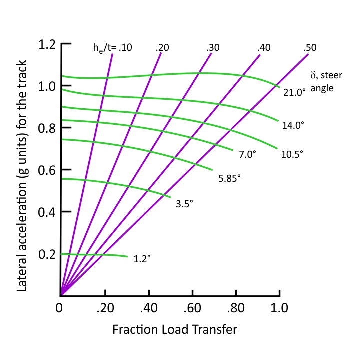
Figure 2. Potential Diagram. (MILLIKEN & MILLIKEN, Race Car Vehicle Dynamics – Adapted)
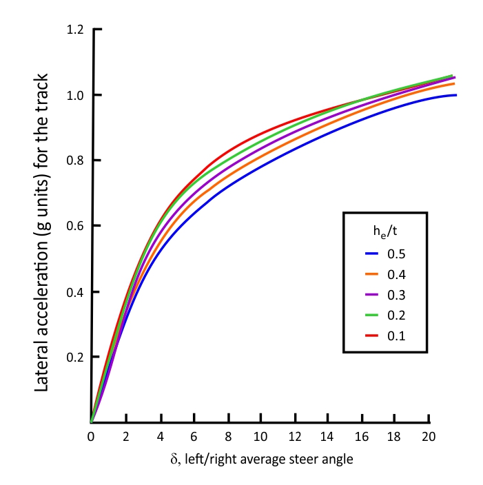
Figure 3. Cornering coefficient curve for a track. (MILLIKEN & MILLIKEN, Race Car Vehicle Dynamics – Adapted)
The potential diagram is a benchmarking of the performance that can be achieved by a pair of tyres. Bear in mind that the lateral acceleration obtained from a specific fraction load transfer value will not necessarily cause the correspondent load transfer on the axle. The inputs are essentially the loads and orientations of the tyres, and the outputs are given per unit weight on the axle, allowing for a vehicle-independent analysis. The diagonal lines represent lateral force potential for constant values, whereas the curved lines show values obtained for a constant reference steer angle.
In the post about lateral force from the tyres, we discussed tyre load sensitivity, the property that makes lateral force from a tyre to grow at a smaller rate with increasing vertical load. This will have a net effect of decreasing the lateral force generated by an axle when the load transfer on it increases. This characteristic is also observed here. If you analyse figure 2, you will see that an increasing fraction load transfer will come together with a decreasing lateral force potential for the axle.
In figure 3 the effect is repeated, but from a different perspective. Here, the load transfer is increased by means of the lateral load transfer parameter, instead of the FLT. Notice the smaller cornering potential for higher values of the lateral load transfer parameter.
The 3 Mechanisms of Lateral Load Transfer

Speedsport Magazine
As stated before, it is very difficult to change the total lateral load transfer of a car without increasing the track width or reducing either the weight or the CG height. However, the suspension of a car will allow lateral load transfer to present itself in different ways and to be distributed between the axles in a controlled manner.
In this analysis, we will be interested in lateral load transfer in a single axle, and I will discuss the three mechanisms by which that happens, namely, roll resistance moment from springs and antiroll bars, direct lateral force load transfer and lateral load transfer from unsprung mass.
All these mechanisms generate a moment about the car that will translate into a vertical load difference between the inside and the outside tyres. Before we discuss how these moments are quantified, it’s interesting to derive a relation between a generic moment  and the vertical load change between tyres separated by a distance . Refer again to figure 1. The moment equilibrium analysis will be the same here, but we will substitute the moment from the inertial force about the CG,
  , by a generic moment, . The result will be:

Now we know that the load transfer caused by a generic moment about a track will be the moment divided by the track width, and we can use that to analyse the effect of each component of load transfer. Referring back to the total load transfer equation, we see that the total weight transfer will be caused by inertial forces acting upon the entire mass of the car. We can split the inertial force into sprung and unsprung components and we will have the following relation:
Where  is the moment acting upon the sprung mass and
  is the moment on the unsprung mass. A more in-depth discussion on how each of these moments are generated will now be presented. After that, we will see how the components of load transfer can be manipulated to tune the balance of the car.
#1 Lateral Load Transfer from Unsprung Mass
Avian Photography
The simplest component of load transfer is the one related to unsprung mass. If unsprung mass is isolated, it’s possible to find its own CG. When the car corners, lateral acceleration is applied at this CG, generating a centrifugal force. This force will result in a moment, whose arm is the unsprung CG height,  . The moment can be divided by the axle track to yield a lateral load transfer component:
Where  is the unsprung weight on the track being analysed.
This component of lateral load transfer is the least useful as a setup tool. Changing the moment generated by this component requires changes in either the unsprung mass or its CG height. Both of these changes will involve adding, removing or repositioning mass (and therefore parts) within the unsprung part of the car. This could affect wheel hop (the ride mode that characterises oscillation of the unsprung mass between the road surface and the sprung mass) frequency and amplitude, reducing the contact of the tyres with the ground and hence, reducing grip. This component will, however, be altered by changes in other components (e.g. replacement of brake cooling ducts for a lighter/heavier version).
#2 Load Transfer from Direct Lateral Force (or Kinematic Load Transfer Component)
F1 Technical
Before we start this analysis, let’s make some important definitions:
-
- The Roll Centre of an axle is the point on the transversal vertical plane passing through the wheel centres of an axle, where a lateral force is applied to the sprung mass without producing any roll. It’s also the point through which the lateral force applied to the sprung mass is transferred to the unsprung mass, i.e. the roll centre is the force coupling point between sprung and unsprung mass.
- The Neutral Roll Axis, or just roll axis, is the line that connects the roll centres from front and rear suspensions.
Load transfer from direct force is one of the two components related to the lateral force acting upon the sprung mass. It arises from the force coupling effect that roll centres have, directly linking forces on sprung mass to the unsprung mass. It’s also called the kinematic load transfer component, because the roll centres are defined by the suspension kinematics. Here, the lateral force acting on the sprung mass ( ) will generate a moment on the tyres through the roll centre height that will also contribute to lateral load transfer. This is given by:
Here,  is the sprung weight distribution to the axle being analysed and
  is the roll centre height for the track. Sprung weight distribution is calculated as the ratio between the distance from the sprung weight CG to the axle opposite to the one being analysed,
  , and the wheelbase of the vehicle
  , times the sprung weight
  .
.

The equation for this component can then be expanded:
Because the force coupling nature of roll centres is not as widely known as the definition of the term roll centre itself, some people are unaware of this component. This leads some to think that increasing roll centre heights will actually decrease weight transfer because it reduces roll. The thing is, roll is only one part of the equation, and as the discussion on this post will show, increasing roll centre height might either increase or decrease the lateral load transfer, depending on other parameters.
#3 Load Transfer Due to Roll Angle (or Elastic Load Transfer Component)

Racin’ Today
When the vehicle is cornering, the centrifugal force from inertia generates a moment that makes the sprung mass roll to the outside of the corner. When this happens, the outside spring of the suspension is compressed and the inside spring is extended.
Since springs are devices that generate forces upon displacements, a force on each spring arises, and these forces generate a moment that tends to resist the rotation of the body. The forces upon the springs are reacted by the tyres, and that contributes to lateral load transfer. Because of this interaction with the springs, this component is also referred as the elastic weight transfer component. Also, when the chassis rolls, the CG of the sprung mass will be shifted sideward, and that will give rise to another moment that will add to lateral load transfer.
When cornering, the sprung mass of the car will roll by an amount  , the roll angle. This is reacted by the roll stiffness (or roll rate),
  , of the car. Roll stiffness is defined as the resistance moment generated per unit of roll angle of the sprung mass, and it has SI units of Nm/rad. On independent suspension vehicles, roll stiffness is a function of the vertical stiffness of the suspension (ride rate, which includes tyre stiffness) and track width.
Antiroll bars are generally added to the car to make it stiffer in roll without altering the ride characteristics. The roll stiffness of the car is the sum of roll stiffnesses of front and rear axles:
One important thing to notice is that the chassis is assumed a rigid body, and hence, the roll angle is the same for front and rear suspensions. Thus, the roll resistance moment is given by:

Now, let’s move on with the calculations, by making some assumptions:
-
- A lateral force applied on the roll axis will produce no roll;
-
- Front and rear roll rates are measured separately;
-
- Tyre stiffnesses are included in the roll rates;
-
- Vehicle CG and roll centres are located on the centreline of the car;
- Small angles are assumed, such that
 and
and  .
.
For this analysis, let’s consider the sprung mass in isolation. Figure 4 shows the forces and moments acting on the sprung CG. The views are along the roll axis.
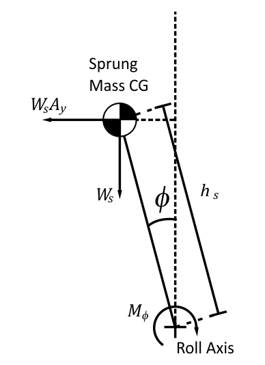
Figure 4. Roll Load Transfer Geometry
Let’s analyse the moment involved in roll. The inertial force acting on the vehicle CG will generate a moment about the roll axis. This moment is called roll moment or roll couple,  , because it is responsible for body roll. The splitting of the roll moment between front and rear axles is useful in analysing lateral load transfer and this is called roll moment distribution between front and rear axles.
The analysis begins by taking the moment equilibrium about the roll axis:

Where is the roll resistance moment, and  is the roll moment. The term
  is a gravity component that arises due to the sprung CG being shifted to the side when the chassis rolls. Applying the small angle assumption, we have:

Substituting the definition of the roll resistance moment in the equation above, we have:

Solving for and dividing by we obtain the roll sensitivity to lateral acceleration of the car, i.e. the amount of body roll per unit of lateral acceleration:
If we isolate the roll angle from the equation above, we can use it to calculate the moments from roll resistance moment and sprung CG side shift for a single axle. In a single axle, the roll resistance moment will be the roll angle multiplied by the roll stiffness of the axle analysed,  .
.

Note that this component resists only roll angle, and the entire sprung mass is used here, as this is how we obtained the expression for roll angle. The same will not be true for the weight shift component, because the axle will only support the fraction of the sprung weight distributed to it. The weight shift component for a single axle will be:
Substituting roll angle on the expression above, we have:
The total moment from roll angle on a single axle will then be:
The lateral load transfer from this moment is obtained by dividing this by the axle track width, t:
Lateral Load Transfer as a Setup Tool

UK2 Group
The three components of lateral load transfer should be added in order to obtain the total lateral load transfer on an axle:

The expression above can be utilized to calculate the load transfer on each axle, which can then be used to improve handling. Now that we have quantified lateral load transfer on an axle, we can start to analyse how the individual components interact.
Before we start, it’s worth to give a note on units. For you to get meaningful results from the equation above, you need to use consistent units. For the SI system, the weights should be in N, the angular stiffnesses in Nm/rad, the lengths in m, and the acceleration is nondimensional (because we are dividing lateral acceleration by the acceleration of gravity).
You already know from steady-state pair analysis and from the discussion on tyre load sensitivity that lateral load transfer will decrease the lateral force capability of the axle. On limit conditions, this will translate in one of the axles “breaking loose” and skidding before the other. If that is the case in the front axle, the car will understeer, if it is in the rear axle, it will oversteer.
We have established that playing with the unsprung weight component is not the smartest thing to do, so let’s focus on the sprung weight components, i.e. the kinematic and elastic components.
Kinematic Load Transfer Component
The first one to analyse is the kinematic or direct lateral force load transfer component. From the general lateral load transfer equation, we know that this component is changed by modifications to either the weight distribution of the car, or the roll centres height. Weight distribution can be controlled through positioning of ballast in the car. Changing weight distribution will obviously alter CG longitudinal location, and that might have undesirable effects on many other aspects of the car. For example, if the weight is shifted forward, the front tyres may be overloaded under heavy braking, while the rear tyres may lose most of their vertical load, reducing the brake capability of the car.
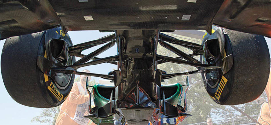
The second option to alter load transfer from direct lateral force component is to change roll centre heights. This is a complex measure because it requires changes in suspension geometry, and it has influence on all geometry-related parameters, such as camber and toe gain, anti-pitch features and so on. This is altered by moving the suspension pickups so that suspension arms will be at different position and/or orientation.
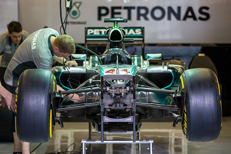
In some categories, the rear suspension is mounted on the gearbox, for example, Formula 3, shown in figure 5. Here the pickup points are highlighted for better comprehension. Figure 6 shows the CAD design of a similar gearbox, highlighting the different options for installing pickup points. As we move up to higher categories, the engineering gets more complex. Figure 7 shows the gearbox from Mercedes W05, 2014 Formula One champion. Here the gearbox has a removable carbon fibre structural outer sleeve, allowing changes in the design of the rear suspension without having to re-test the rear of the car for crashworthiness.
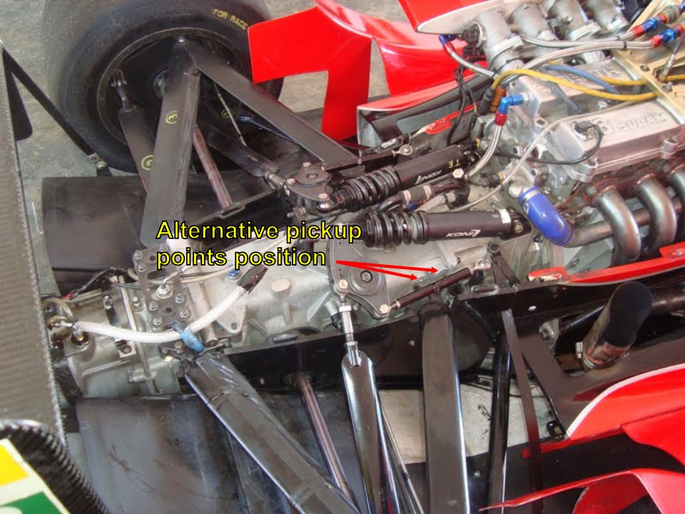
Figure 5. Rear Suspension of a Dallara F308.
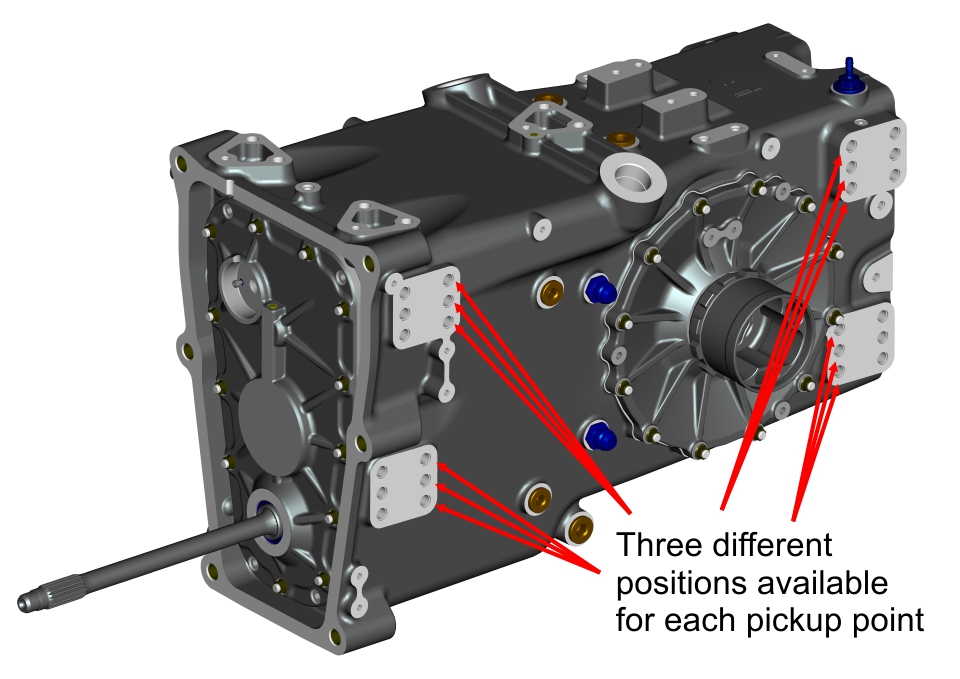
Figure 6. Indy Lights Gearbox (Ricardo Software)
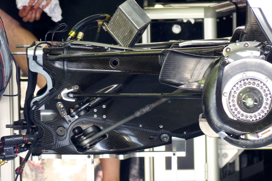
Figure 7. Mercedes W05 Carbon Fibre Gearbox Sleeve for Mounting Suspension Points (F1 Technical).
It’s not possible to conclude directly what influence increasing roll centre heights will have. A quick look at the lateral load transfer equation might lead you to think that lateral load transfer will increase with increasing roll centre heights because of the direct relation in the equation.
The fact is, by increasing the roll centre height in one axle, you are increasing lateral load transfer from the direct lateral force component, while at the same time you are decreasing lateral load transfer from roll angle component. Bear in mind that the roll moment arm  is the perpendicular distance between the CG of the sprung mass and the roll axis. Figure 8 clarifies. The overall effect will depend upon roll centre heights and roll stiffnesses, and a definitive conclusion will require a deeper analysis.
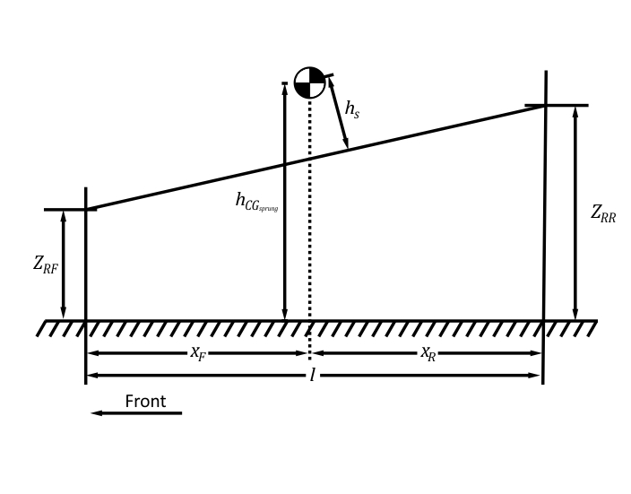
Figure 8. Roll Moment Geometry.
One thing we can tell without any deep analysis is that increasing the roll centre height in one axle decreases the lateral weight transfer on the opposite axle, everything else kept constant. This happens because raising the roll centre in any axle will approximate the roll axis to the sprung weight CG. This will decrease roll angle component, but since the roll centre height of the opposite axle will not be raised, the direct lateral force component will not increase and the overall effect will be a reduction in weight transfer on that axle.
To further expand our analysis, let’s put the theory into practice. Figure 9 shows a contour plot of lateral weight transfer sensitivity (lateral weight transfer divided by lateral acceleration) on both axles of an open wheel single-seater. To obtain these, I created a MATLAB routine to calculate the total lateral weight transfer from our previous discussion, keeping the front and rear roll stiffnesses equal and constant while varying front and rear roll centre heights. The input data were based on the manuals from the manufacturer of an important formula category.
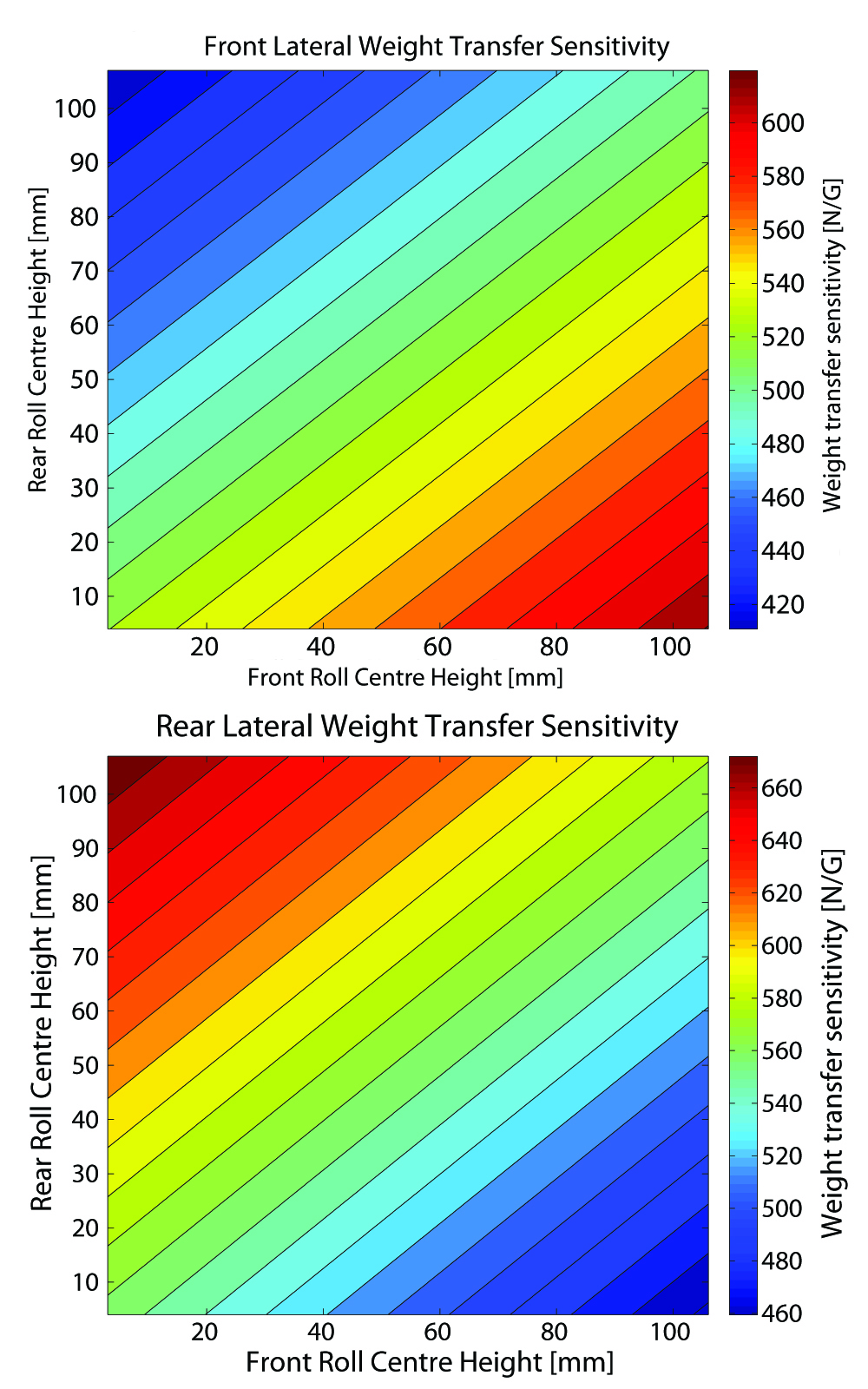
Figure 9. Lateral weight transfer sensitivity to roll centre heights.
By analysing Figure 9 you can see that lateral load transfer is very sensitive to changes in roll centre height. For example, if you investigate what would happen to the weight transfer in both axles if you held rear roll centre height constant at 30 mm while increasing the front roll centre height, you would see opposite effects happening on front and rear tracks (weight transfer would decrease in the rear axle while increasing in the front).
Try this exercise: pick whatever value you want for rear roll centre height, and imagine an horizontal line passing through the point correspondent to that value in both graphs, and observe how weight transfer changes along this line in both graphs (remember each graph represents an axle). Now do the same, but picking a front roll centre height and imagining a vertical line instead. What happened?
As you see, when we increase front roll centre height, the lateral weight transfer decreases on the rear axle while increasing on the front. Conversely, if you increase rear roll centre height, lateral load transfer increases on the rear axle and decreases on the front axle. Can you see the trend?
When you increase roll centre height in one axle you increase the overall lateral load transfer on that axle, while decreasing it on the opposite axle. This leads as to believe that the roll centre height gain is higher than the decrease in the roll moment arm . The change in this arm with roll centre heights will depend on the wheelbase and weight distribution.
The calculations presented here were based on a vehicle with a 3125 mm wheelbase and 54% weight distribution on the rear axle, which are reasonable values for most race cars. For this case, roll moment arm decrease with roll centre heights was smaller than the increase in roll centre heights themselves. In my time in Baja, I have done calculations of the type for vehicles that had roughly the same weight distribution and wheelbases of approximately 1500 mm. The results were the same. I make no claim that this would hold true for every car in the world, but if that’s the case for vehicles with wheelbases as different as the ones I’ve tried, than I wouldn’t be surprised if it was for other cars.
Elastic Load Transfer Component
This component is the easier to control. Let’s repeat the weight transfer equation here to make things easier:
By looking at the equation, you can see that the weight transfer component from roll angle can be altered by changes in front or rear roll stiffnesses, roll moment arm or weight distribution. Now let’s stop for a moment to analyse the influence of the gravity term  on the lateral load transfer component.
As we discussed, we should input consistent units into the equation to obtain meaningful results. The manual of the vehicle used here specified a roll stiffness values ranging from 350,000 Nm/rad to 5,600,000 Nm/rad. The sprung mass used was 675 kg, which gives a weight of 6621.75 N. With a CG height of 254 mm and the minimum roll centres specified in 3 mm, which is very low, the moment arm will be 251 mm. With those values, the gravity term will be 1662.1 Nm. Do you see how small it is compared to the roll stiffness of the car?
You might not be convinced of the insignificance of this term by arguing that those values were obtained for a very light car with a very low CG. So let’s try it with a 1200 kg vehicle with CG height varying from 100 mm to 1 m (which is ridiculously high even for a road car). Figure 10 shows the plot of the roll angle component versus gravity term.
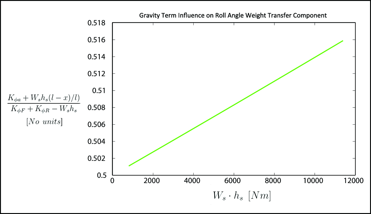
Figure 10. Gravity Term Influence on Roll Angle Weight Transfer Component.
Varying the gravity term from 800 Nm to 11395 Nm resulted in a difference of only 0.0148 (from 0.5011 to 0.5159) or 2.96 %. Bear in mind that these values were obtained for a fairly heavy race car with an unreasonably high CG, and this is only one of three weight transfer components.
At this moment, you should be convinced of the irrelevance of the gravity term on roll angle weight transfer component. This basically rules out weight distribution as a way of controlling roll angle component. We now have roll moment arm and roll stiffnesses to play with. From our previous discussion on direct force weight transfer component, you know that to change roll moment arm you need to play with roll centre heights, which will ultimately affect that weight transfer component in the opposite way you want.
Another reason to rule out changes in roll moment arm is that, because it directly multiplies the proportion of roll stiffnesses, it will have the same effect on both axles whether is to increase or decrease lateral load transfer. For setup, we look into changing the lateral load transfer in one axle relative to the other, to affect balance. This makes changes in roll moment arm to control roll angle component useless. Let’s now analyse roll stiffnesses.
Roll stiffness can be altered by either changing ride stiffness of the suspension (vertical stiffness) or by changing the stiffness of the antiroll bars. Ride stiffness can be altered by either changing springs or tyre pressures (tyre pressure affects tyre stiffness, which contributes to the overall ride stiffness). This is generally not the first option to take because of the effect that it has on other aspects of the car.
For the sake of example, ride stiffness controls ride height, which has strong effects on aerodynamics of ground effect cars (almost every race car with relevant aerodynamics design). Another example would be the effect of ride stiffness on wheel hop frequency. Hence, springs and tyre pressures should only be changed when other aspects need modification, but not only roll stiffness itself (unless the vehicle has no antiroll bar).
The most reasonable option would be changes on antiroll bar stiffness. This can be done in multiple ways. The hardest one would be to change the bar itself, though there are some antiroll bars that have adjustable stiffnesses, eliminating the need to replace bars. These adjustable bars generally have blade lever arms, as the one shown in figure 11.
Figure 11. Adjustable blade antiroll bar (Proven Wicked).
By rotating the lever arms, its area moment of inertia in bending is changed, hence altering its stiffness. Figure 12 shows a finite element stress analysis, with colours closer to yellow and green indicating higher stresses. Some race cars have push-pull cables connected to the bars that allow the driver to change roll stiffnesses from inside the car.
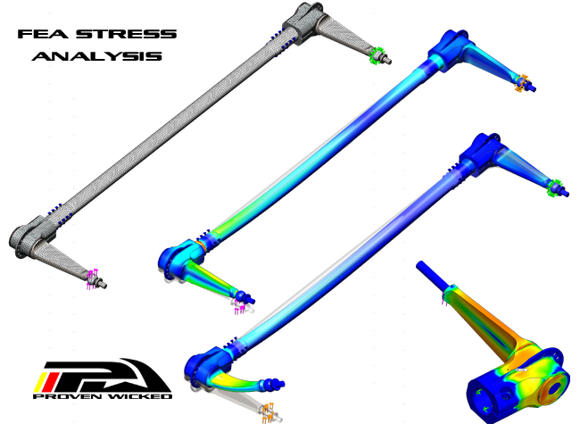
Figure 12. FEA stress analysis of a blade antiroll bar (Proven Wicked).
Now that we know the best ways to change roll stiffness, let’s see how it affects lateral load transfer. Figure 13 shows the contour plots of lateral weight transfer sensitivity as a function of front and rear roll stiffnesses. These data were obtained for the same open wheel car analysed in figure 9, but this time front and rear roll centres heights were held constant and equal, while roll stiffnesses varied. The stiffnesses are shown in kgfm/degree, that have clearer meaning, but the data were input in Nm/rad.
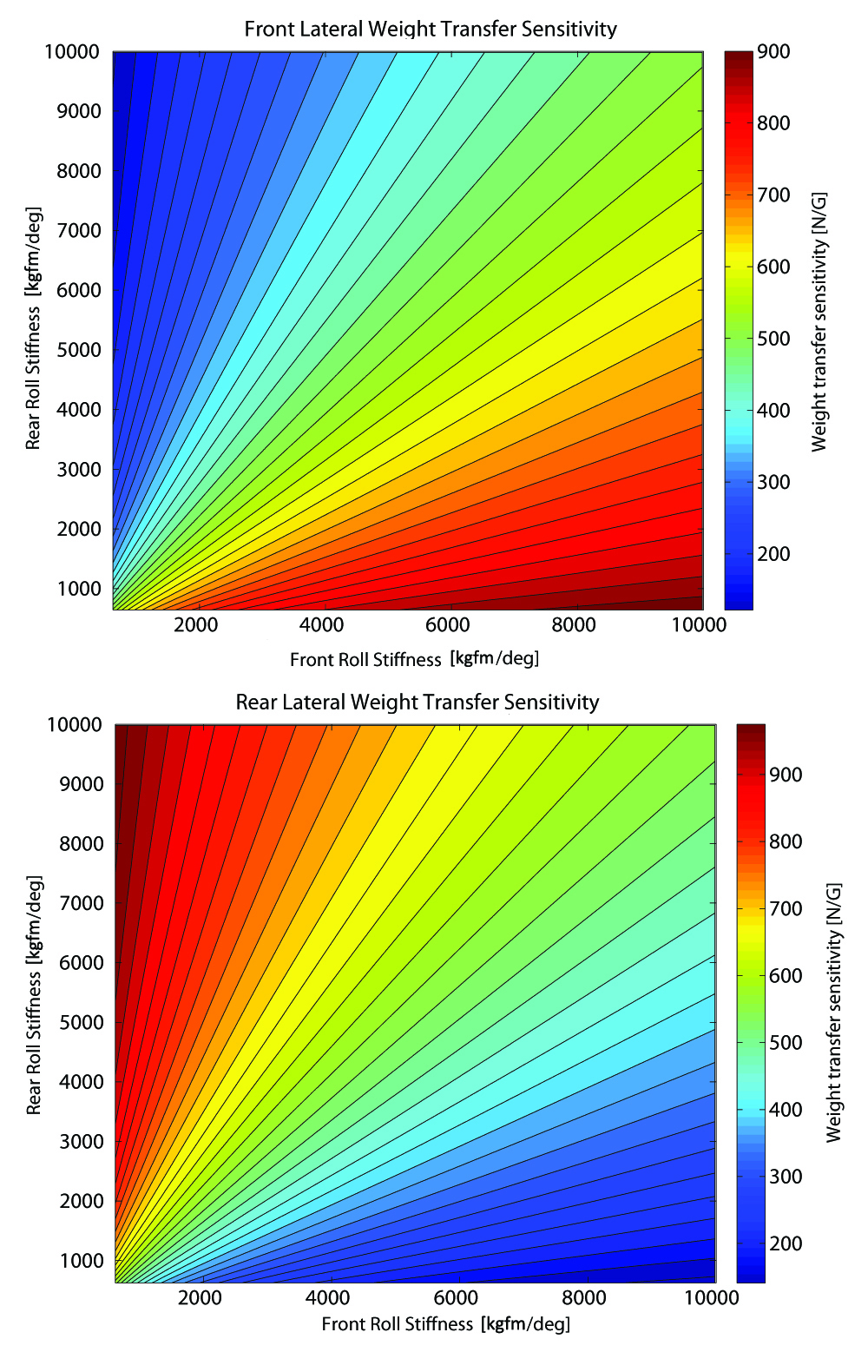
Figure 13. Lateral weight transfer sensitivity to roll stiffnesses.
If you compare figures 13 and 8, you will see that, while lateral weight transfer changes with roll centre heights along contours defined by lines that have the same inclination, the effect is different with respect to roll stiffnesses, as the lines that limit the contours have different inclinations.
If you represent the rear roll stiffness as proportion of front roll stiffness in a line plot, the result will be a straight line, with an inclination equal to the proportion between the roll stiffnesses. If you represent multiple proportions, you will have multiple lines with different inclinations. Do you see where this heading? Lateral load transfer in one axle will change with the proportion of the roll stiffnesses on that axle, not the roll stiffnesses themselves.
This can be confirmed by adopting the conclusions from the analysis of figure 10, where we agreed that the gravity term is negligible for roll angle lateral weight transfer component. If we use  , the remaining roll angle component will be:
If we keep the roll moment arm constant, then roll angle lateral load transfer component in one track will obviously be a function of the ratio between the roll stiffness on that track and the total roll stiffness of the car. The term between brackets in the equation above is the roll rate distribution or roll stiffness distribution for a given axle, and it will ultimately control the elastic lateral load transfer component.
Elastic and Kinematic Components Combined
So far, we have discussed the influence of each component in lateral load transfer in isolation. Let’s now see how these components affect each other and how they affect load transfer together. For this analysis, only the rear axle was considered. The front and rear roll centres heights were kept equal, but varied from 3 mm to the CG height (254 mm). The weight distribution on the rear axle was 54 %. Roll stiffnesses were input in the form of roll rate distribution, varying from 0 to 1. Figure 14 shows the contour plot.
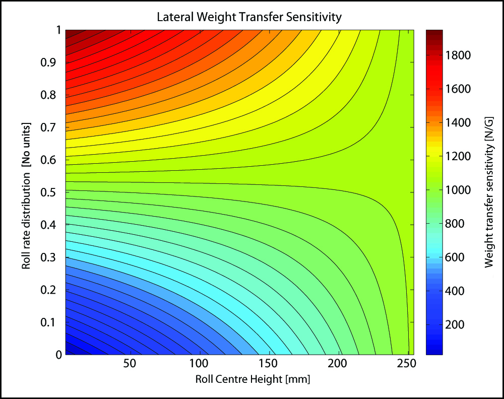
Figure 14. Lateral weight transfer sensitivity to roll rate distribution and roll centre heights.
Figure 14 can lead us to very interesting conclusions. First notice that there are two particular regions in the plot, where any changes to one of the components will produce no sensitive effect on weight transfer. This is characterised by the green region in the graph. If you hold rear roll rate distribution constant at 54 % and increase roll centre height, lateral load transfer will have no significant change. Conversely, if you hold roll centre heights at about 254 mm and vary rear roll rate distribution, lateral load distribution won’t suffer relevant differences. What happened here?
If we define  , the rear roll rate distribution and
  , the sprung weight distribution on the rear axle, then the lateral load transfer equation for that axle can be rewritten to give:

First, let’s analyse what happens when we hold roll rate distribution equal to the weight distribution on that axle. Substituting the values on the terms inside the brackets, we have:

But if we assume that front and rear roll centers have the same height, then the moment arm will be given by:

Substituting into the weight transfer equation yields:
This shows that when weight distribution and roll rate distribution are equal, for a horizontal roll axis, the sprung weight load transfer component will be independent of roll centres heights. Notice that this conclusion doesn’t necessarily hold true for different roll axis inclinations.
Now let’s analyse what happens when roll centre heights get close to the CG height. If  , and will have the term inside brackets resulting in
  .
.
This will tell us that lateral load transfer on a track will become less dependent on the roll rate distribution on that track as the roll axis gets close to the CG of the sprung mass. This conclusion is somehow trivial, as we know that roll moment arm decreases as roll axis gets closer to the sprung mass CG and roll rate distribution only affects the roll angle lateral load transfer component.
Now let’s use the knowledge discussed here applied in the example presented at the beginning of this article, with a little more detail in it. Let’s say the car is rear wheel drive with a rear weight distribution and large, lightly loaded tyres. If your driver complies about oversteer in the slowest corners, it means that the front axle is generating higher lateral force than the rear. By the methods presented here, the simplest solution would be shifting roll rate distribution to the front, by either stiffening the front antiroll bar or softening the rear. In order words, the goal would be to reduce lateral load transfer in the rear axle in comparison to the front axle.
If that solution doesn’t work, you could have roll centre heights that would give a roll axis too close to the sprung CG, as discussed before. If that was the case, you should work on the roll centres heights instead, and then adjust suspension parameters accordingly. Again, if that doesn’t work, then lateral load transfer will not be the right parameter to change.
Bear in mind that lateral load transfer affects the balance through tyre load sensitivity (the tendency of the tyres to generate higher lateral forces at a decreasing rate with higher vertical loads). If the tyres of the car are lightly loaded, there might not be enough load sensitivity in the tyres, so that even if one end of the car takes all the lateral load transfer, the lateral force performance isn’t degraded significantly.
In that case, changing roll rate distribution or roll centre heights will have little effect in the balance, and other alternatives must be looked at, such as adjusting tyre pressures, tyre size and/or width or moving CG location (so that the inertial forces will be different in each axle). Notice that this is just one possibility and other parameters might be investigated as well.
A Summary of What You’ve Read

Zimbio
-
- We used steady-state pair analysis to show once again that lateral load transfer in one end of the car decreases the capability of that end to generate lateral force.
-
- We derived the equations of lateral load transfer in one axle of the car, showing that it’s composed of three components:
-
-
- Unsprung weight component – not useful as a setup tool because of the effect that it has on ride, specifically wheel hop mode.
-
-
-
- Direct force component or kinematic component – useful as a setup tool, especially when roll axis is close to the sprung CG, and the influence of roll component is reduced.
-
-
-
- Roll angle component or elastic component – the most useful component as a setup tool, since it is the easiest to change when antiroll devices are present. It has increased importance when roll rate distribution in one track gets close to the weight distribution on that axle, as direct force component has its importance reduced (assuming horizontal roll axis).
-
- If changes to lateral load transfer have not significant effects on the balance of the car, this might be an indication that the tyres are lightly loaded, and load sensitivity is small.
Bear in mind that all the analysis done here was for steady-state lateral load transfer, which is why dampers were not mentioned at all. Transient lateral load transfer is an important aspect of vehicle setup, but let’s leave the discussion on that for another day.
I hope this article was useful to you, and that you have enjoyed reading it.
Please, leave a comment below, to let me know what you liked most in this article or what else you would like to know about the subject, or even some criticism or any knowledge you might want to share.
Also, if you liked this post, please share it on Twitter or Facebook, and among your friends. See you soon!