Author unknown
This is it! The first post on Racing Car Dynamics. There is just no better way to start a discussion on race car dynamics than beginning by the tyres. Those small rubber components are the only contact the car has with the track, and the only way the driver has to ensure the car is following the intended direction. Racing tyres are the driver’s best friends, as once said the racing world legend Carroll Smith.
Being complex as they are, it is impossible or at least not smart to tackle them as a whole. That is why this article is actually going to be the first of a series of posts, each of them focusing on specific aspects of the racing tyre. To begin with, I am going to talk about its most important characteristic (assuming we are talking about circuit racing tyres): the generation of lateral force.
Friction Generation Mechanics
First, let us make some things clear. The force generated between the tyre and the track is not friction in its strict sense. The traditional Coulomb friction theory says that friction is proportional to vertical load on a body, independently of the contact area. This model is good for a great range of physics and engineering applications, but this is not the case for tyres.
The generation of lateral force (which only exists because of “friction” between the tyre and road) of tyres is strongly dependent on vertical load, but also on tyre width, size and pressure, which clearly are related to the contact area between tyre tread and the road. With that said, I will use the terms “friction” or “grip” referring to the force that arises in the interface of the tyre with the track, since this is the term used in most of the literature on the matter.
The forces generated on tyre-track interface arise mainly due to two mechanisms: adhesion and hysteresis. The adhesion rises from the intermolecular bond between the tyre rubber and the aggregate in track surface. It is the larger of the components on a dry track surface, but it is significantly reduced under wet track conditions, hence the grip reduction on raining conditions.
To explain how hysteresis gives rises to grip between the tyre and the track, I will first clarify what hysteresis is. In terms of tyres, hysteresis is the tendency of the rubber to have a delayed return to the natural state after suffering a deformation. Confusing? A little bit. Let’s make things a little bit clearer: if you press your fingernail against a street-spec low hysteresis tyre’s tread, the rubber will return quickly to its natural state. Do the same with race-spec high hysteresis tyre and the mark will stay there for a few seconds, returning much slower.
But how does hysteresis generates grip? Well, when the tyre deforms, it stores elastic potential energy, which is released upon returning to the neutral state. With hysteresis, energy is lost (converted into heat) when the rubber is on relaxation phase, and hence a resistive force arises between the tread and the road. The exact mechanism of how this force arises is not fully understood, but Paul Haney gives a good insight in his book “The Racing & High-Performance Tires: Using Tires to Tune for Grip and Balance”:
“Consider Fig […] where there is some sliding between the rubber and an irregular surface. If the rubber recovers slowly from passing the irregularity as in the high-hysteresis rubber, it can’t push on the downstream surfaces of the irregularities as hard as it pushes on the upstream surfaces. This pressure difference between the upstream and downstream faces of the irregularity results in friction forces even when the surfaces are lubricated.” The mechanism in question is shown in Figure 1, originally taken from Haney’s Book.
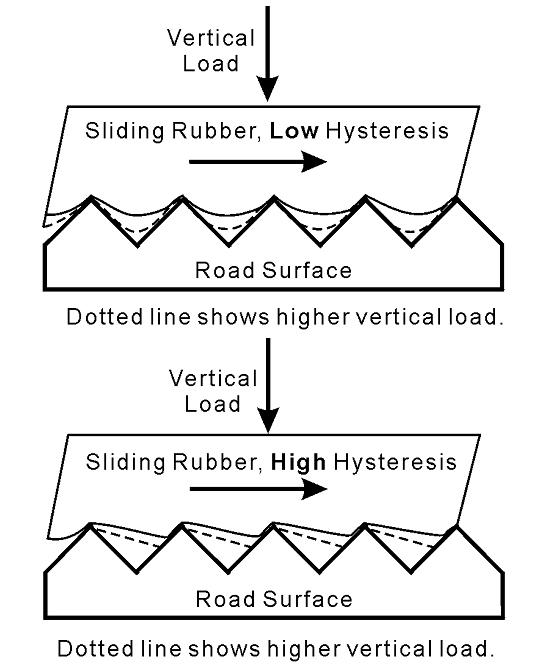
FIGURE 1. Hysteresis in sliding rubber. (HANEY, Paul, The Racing & High-Performance Tires: Using Tires to Tune for Grip and Balance)
Lateral Deflection and Slip Angle
When the driver turns the steering wheel, the car initiates negotiating the corner. Shortly after this happens, the inertia of the car generates a centrifugal force or inertial force that pushes the car outside the corner. This force (which is not a real force, but instead an apparent force since it arises only due to inertial effects) is also transmitted to the tyres, causing a lateral deflection on them. Figure 2 illustrates how the tyre will look like after deformed.
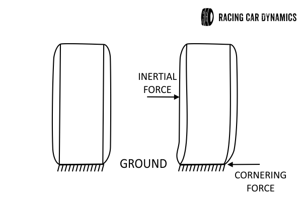
FIGURE 2. Tyre in upright zero slip condition (left); Tyre deflected after lateral deflection caused by inertial forces (right).
The lateral deflection happens for two reasons: first, the tyre is elastic in twist, i.e. the part of the tyre that is in contact with the road (called contact patch) will not rotate as much as the rest of the tyre (by rotation, I mean the steering rotation of the wheels, about the vertical axis). Since the tyre is elastic, the points in the tyre near the contact patch will also have a lateral deflection.
Once the tyre is rolling, the particles that will be part of the contact patch will be constantly renewed, experiencing side deflection when passing through the contact patch leading edge, its centre and its trailing edge. On the other hand, the particles are attached to each other, and because of that, the deformation begins before the particle reaches the leading edge of the contact patch, and ends after the rubber goes past the contact patch. Figure 3 shows the deformation taking place before, during and after the particle touches the track.
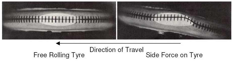 FIGURE 3. Lateral deflection in tyre contact patch and its vicinities. (CLARK, Samuel; 1971, Mechanics of Pneumatic Tires).
The second reason why lateral deflection happens is because the grip between the tyre and the track prevents the tyre from sliding sideways when the inertial force pushing the tyre outwards the corner is present. This combination of effects makes the tyre travel in a different direction from that the wheels are pointing. Think of it as the following example: if you walk straight ahead, but with each step you move your feet a few inches to the side, the path that your feet will make is going to be at an angle with the direction you are facing. The same happens with the particles in the tyre contact patch.
The angle between the tyre path and the wheel pointing direction is called Slip Angle and it is of fundamental importance for the knowledge of how a race car works during a corner. It is important to notice that no sliding is occurring between the tyre and the track, which makes the term “slip angle” somewhat of a misnomer. However, this is the name used in most of (probably in all) the literature on tyres, vehicle dynamics and race car dynamics and will be used here as well. The first video below shows an experiment in a tyre test rig where is easy to see the slip angle. The second video shows the effect on a real car.
Demonstration of Slip Angle
Slip Angle on a Corvette Z06
Lateral Force
The lateral deflection taking place in the tyres gives rise to an elastic force. This force, called cornering force or lateral force is perpendicular to the direction the wheel is pointing and happens in the center of the tyre contact patch. The relation between lateral force and slip angle is reciprocal: The lateral force can be thought as a result of the slip angle, and the slip angle as a result of lateral force (if the lateral force is increased, the centrifugal force will also increase, generating larger deflections on the tyre, and hence, larger slip angles). Cornering force can be thought as the capacity of the tyre to resist sliding sideways when in a corner.
The lateral force will increase with slip angle, and both will grow by decreasing the turn radius or increasing the vehicle’s linear speed (both of these conditions represent a growth in lateral acceleration). As the slip angle increases, some sliding begins to occur in the tyre tread. If the slip angle is further augmented, eventually the tyre will “break loose” and sliding will occur in the entire contact patch.
The three ranges of tyre behaviour in a corner, namely, no sliding, some sliding and total sliding in the contact patch are called, elastic, transitional and frictional ranges of tyre operation, respectively. When in the frictional range, the sliding friction between the tyre and the track is the only cornering force present, and is no longer caused by tread distortion. Figure 4 shows the relation between lateral force and slip angle in a graph, where it is possible to see the three operational ranges. The slope of the of the curve on the linear (elastic) range is called the cornering stiffness of the tyre, and it is an important parameter for the analysis of cornering behaviour of the vehicle. We will deal with that on later post.
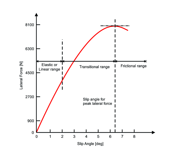
FIGURE 4. Lateral force vs slip angle for a normal load of 8000 N. (MILLIKEN & MILLIKEN, Race Car Vehicle Dynamics – Adapted)
The equation below shows the mathematical relation between the lateral force generated by the tyre (Fy), the slip angle (alpha) and cornering stiffness (C) of the tyre.
The peak of the curve will determine how much lateral force a tyre can produce. This force is called the limit of adhesion. After reaching this limit, the lateral force will decrease, and this will be transmitted to the driver as a light feeling on the steering wheel, indicating that the limit of adhesion has been surpassed. The shape of the curve determines how the car will behave in high acceleration and grip limit situation. For example, take a look at figure 5 below. If the curve has a sharp top, it indicates an abrupt change from transition into a skid, with little warning to the driver. Curves with almost flat top indicate a smoother transition, giving much more warning about the grip situation on the tyres. Unfortunately, the tyres with higher lateral force capabilities (i. e. racing tyres) are the ones with more abrupt transition from grip to skid, and so, the racing driver has to learn how to read that from his steering system.
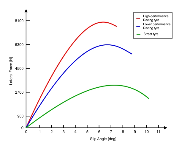
FIGURE 5. Lateral Force vs Slip Angle for three different tyres – the curve is plotted with arbitrary maximum force values, just to show what the line shape should look like. (MILLIKEN & MILLIKEN, Race Car Vehicle Dynamics – Adapted)
An interesting fact about tyres operating at a large slip angle, is that they have a significant resistance to forward motion, and this resistance grows with slip angle. Thus, if power is not applied during such situation, the race car will decelerate, much like hitting the brakes. The technique of using high slip angles to decelerate the car is known as scrubbing off speed. This allows the driver to slow down without actually using the brakes, by throwing the car very hard in a corner, generating high slip angles.
Load Sensitivity
To make things a little bit clearer, let us define the lateral force coefficient. This is analogous to the friction coefficient for friction. All in all, it is just a way of normalizing (or nondimensionalizing) the lateral force. The mathematical definition is as follows:
Where LFC is the lateral force coefficient, Fy is the lateral force and Fz is the vertical load on the tyre. Now, if a tyre is tested to obtain the lateral force vs slip angle curve with several vertical loads, the result is somewhat as in figure 6.
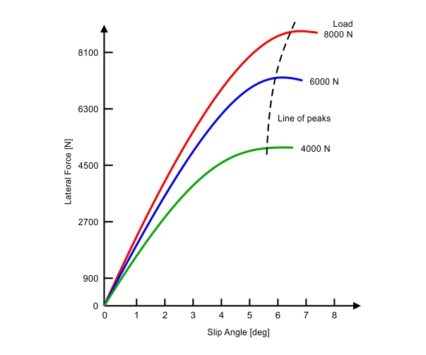
FIGURE 6. Lateral Force vs Slip Angle for several vertical loads. (MILLIKEN & MILLIKEN, Race Car Vehicle Dynamics – Adapted)
If, instead of plotting lateral force we plotted lateral force coefficient (normalized lateral force), the results would be as shown in figure 7.
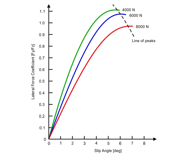
FIGURE 7. Lateral force coefficient vs slip angle for several vertical loads. (MILLIKEN & MILLIKEN, Race Car Vehicle Dynamics – Adapted)
This graph can provide a lot of information. As you can see, the lateral force coefficient actually decreases by increasing vertical load. On the other hand, cornering stiffness grows (slope of linear range on figure 6) with higher vertical forces. By comparing figures 6 and 7 we can see that the ratio Fy/Fz decreases, but the lateral force continues to increase, as vertical load is augmented. The overall outcome is lateral force increasing at a smaller rate at higher vertical loads, and that results in a nonlinear relation between vertical load and lateral force as shown in figure 8.
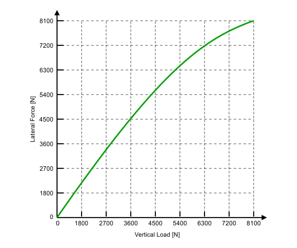
FIGURE 8. Lateral force vs vertical load for a single slip angle value. (MILLIKEN & MILLIKEN, Race Car Vehicle Dynamics – Adapted)
From analysing figure 8, it is possible to get important conclusions on the behaviour of a pair of tyres acting parallel to each other, as in the front or rear axles. Under lateral accelerations, there will be a load transfer on the axle from the inside tyre to the outside one. The overall vertical load on the axle will remain the same, yet the total lateral force generated by the axle will be smaller than if no lateral load transfer had occurred.
Complicated? Then let’s take the example in figure 8 to understand better what happened. Let’s say a formula car has a 367 kgf (about 3600 N) weight on each of the rear tires. The theoretical lateral force generation that we could obtain from a single tyre looking at figure 8 is about 4500 N, and hence the lateral force capability of the axle would be 9000 N. If we have a 50% lateral load transfer on the rear, then the outside wheel would have a load of 367 + (0.5 x 367) = 550.5 kgf (about 5400 N), while the inside wheel would end up with only 183.5 kgf (about 1800 N) of vertical load.
By looking at figure 8 again, it is possible to see that total lateral force that could be generated by the outside tyre under these conditions would be about 6500 N, while the inside tyre would generate only 2200 N. The total lateral force generated would then be 8700 N, and we would have lost lateral force capability. The curve here is arbitrary, and so are the values, but the general behaviour of the tyre regarding vertical load holds true. This behaviour of an axle under lateral load transfer is crucial for the race car handling, and will be later used in the design and setup of the car to alter its directional behaviour. This will also be discussed in a later post.
On the next post on race car vehicle dynamics, I will talk about the principles behind oversteer and behaviour of the car, and how the suspension affects it. Do you wanna miss that? I bet you don’t! Then, please subscribe to our email newsletter below. See ya! 🙂